NaviTrack® II
Advantages of the Omnidirectional Antenna
Unlike the coils used in many locator devices, the Omni- directional antenna detects fields on three separate axes, and can combine these signals into a “picture” of the ap- parent strength, orientation and direction of a field. Omni- directional antennas offer definite advantages:
The Mapping Display
The mapping display enabled by the Omnidirectional an- tennas provides a graphic view of a signal’s character- istics and a bird’s eye view of the signal underground. It is used as a guide for tracing underground lines and can be used to better pinpoint Sondes. It can also be used to provide more information for complex locates.
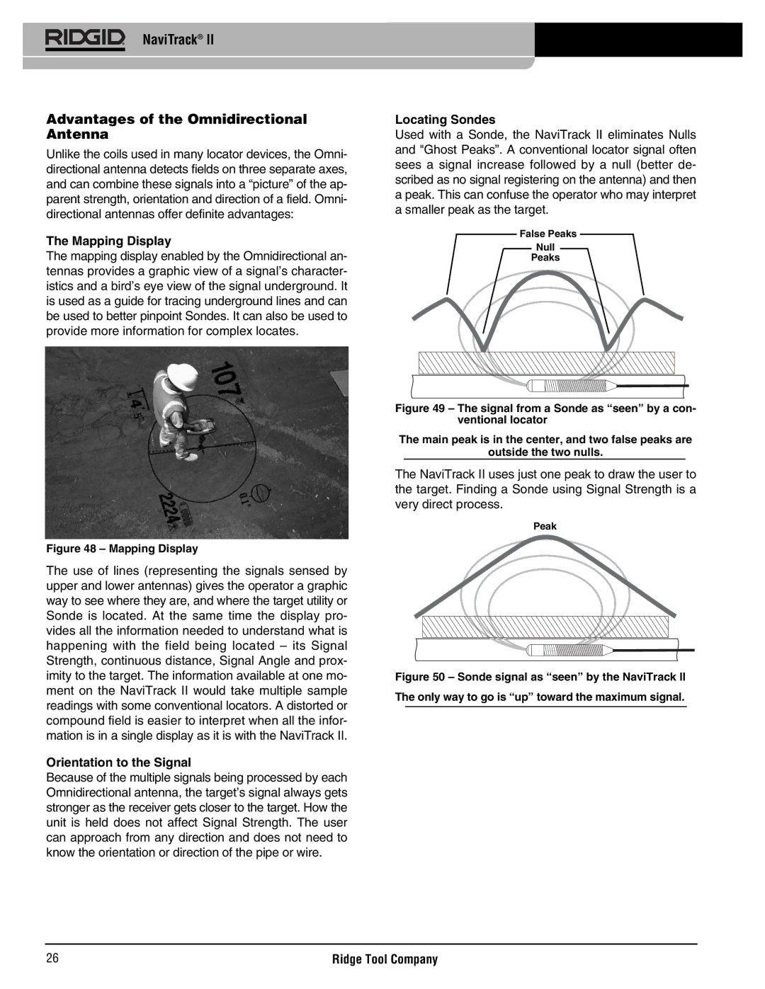
Figure 48 – Mapping Display
The use of lines (representing the signals sensed by upper and lower antennas) gives the operator a graphic way to see where they are, and where the target utility or Sonde is located. At the same time the display pro- vides all the information needed to understand what is happening with the field being located – its Signal Strength, continuous distance, Signal Angle and prox- imity to the target. The information available at one mo- ment on the NaviTrack II would take multiple sample readings with some conventional locators. A distorted or compound field is easier to interpret when all the infor- mation is in a single display as it is with the NaviTrack II.
Orientation to the Signal
Because of the multiple signals being processed by each Omnidirectional antenna, the target’s signal always gets stronger as the receiver gets closer to the target. How the unit is held does not affect Signal Strength. The user can approach from any direction and does not need to know the orientation or direction of the pipe or wire.
Locating Sondes
Used with a Sonde, the NaviTrack II eliminates Nulls and "Ghost Peaks”. A conventional locator signal often sees a signal increase followed by a null (better de- scribed as no signal registering on the antenna) and then a peak. This can confuse the operator who may interpret a smaller peak as the target.
False Peaks
Null
Peaks
Figure 49 – The signal from a Sonde as “seen” by a con- ventional locator
The main peak is in the center, and two false peaks are
outside the two nulls.
The NaviTrack II uses just one peak to draw the user to the target. Finding a Sonde using Signal Strength is a very direct process.
Peak
Figure 50 – Sonde signal as “seen” by the NaviTrack II
The only way to go is “up” toward the maximum signal.
26 | Ridge Tool Company |