DSR-2116 DSR-2108
Table of Contents
Safety precautions
Licensed Under U.S. Patent No ,974,088
Safety precautions
BDisassembly prohibited
BDo not touch the power plug with wet hands
BDo not use during thunder/thunder storms
BDo not place in an unstable position
BDo not sit on
BCleaning the internal components
BWhen the unit is set up in a rack
BDo not expose to extreme temperatures or humidity changes
BDo not block the cooling fans or air ducts
Battery fluid leaks
When disposing of this unit
Main Features Accessories
Main parts replacement timings
Power cable ×2 Remote control
Check that all the parts shown below are supplied
About the split screen display
Do not expose to shock or vibration
Names and functions of parts
Cooling fan Power socket
Names of each part and connections
LAN connection BUsing the switching hub
BWithout using a switching hub
Names of each part and connections
Internet DHCP, Adsl connection
If a system controller is connected
If a camera is connected
Sanyo SSP
Except Sanyo
Switching the power on / off
Switching the power on
Switching the power off
Pre-operation preparation
BExample of multi-16 screen
BExample of single-screen
Settingoutput the television system and the monitor
Setting the clock Clock SET
Pre-operation preparation
BMatching the television system of the camera PAL
Ohters
OFF
USA
Setting the language Language
Setting the RS-485 termination switch Sanyo SSP side
BCorrecting the set time
Language selection
Monitoring the camera videos
Single-screen display
Quad-screen display
Monitoring the camera videos
Camera sequencing
Press the Multi button
Press the SEQ button once operations are complete
Settings
Operating the PTZ dome camera
Connection Operation
Camera menu settings
Operating the PTZ dome camera
Iris/Tour/Sequence operations
Recording
Recording
Continuous recording
Motion recording
Alarm recording
Set the following items using the control button ~
Resolution Frame Rate
Schedule recording
Channel Quality
BCopying a set recording schedule to other channels
Press the EXIT/STOP button
Playing back recorded videos
Playing back recorded videos
If the 4 letters are displayed in red, all the type
Recordings have been selected
Example
Move the cursor to the day of the first recording
Month displayed by the calendar, pressing
Button displays the previous month of the calendar
Memo To play the video of all the channels simultaneously
Press the Search button
Search menu screen is displayed
Press the Enter button. Playback starts
First recording is played back
Press the Search button. The menu is displayed
List is displayed
Still image is displayed
Copying recorded video to recording media
Inserting recording media
Copying live videos
To copy onto a USB memory
Copying recorded video to recording media
Copying a playback video
Playing back copied videos
Still
Setting the security lock
BSetting a security lock
BCanceling the security lock
Factory default password is
Configuration and function of the Menu settings
BLIVE settings P31 BRECORD settings P35
BSYSTEM settings P37
BNETWORK settings P42
Configuration and function of the Menu settings
BBasic operations of the Main Menu
Main Menu screen is displayed
Record menu is displayed
Live settings
Setting the OSD and OSD Contrast
Setting the Sequence
Setting the Event Beep
Live settings
Setting the Video Loss on
Setting the HDD Error
Setting the Alarm Duration
Setting the Type
Setting the SEQUENCE-DWELL Time
Setting the MON2 Channel
Sets the channel that outputs the video to MON2 terminal
If Sequence is set to OFF
Record settings
Setting the Resolution
Setting the Frame Rate Unit ips
Setting the Quality
Record settings
System settings
Setting the DVR ID
Setting the Load Default
Description confirmation
System settings
Setting an Admin Password
BSettings for no password
Press the Enter button without inputting anything
BRestoring the password input
Setting the User Password
Setting a Network Password
Setting the Date Format
Setting the Clock SET
Setting the RS485 SET
Setting the PTZ Control
Setting a Remote Control ID
BOperating this unit via the remote controller ID Example
Selection 01/02/ .. /99
Network settings
Setting the Port
Setting a Client Access
Setting the Bandwidth Saving
Network settings
Setting the Network Type
BIf selecting Adsl
BIf selecting Dhcp
Setting the Ddns
Confirm the User ID and Password displayed on the screen
BIf selecting LAN
Repeat 2 and change the following as necessary
Setting the Send E-MAIL
Setting the NTP SET
Mail to
Mail Server
Mail from
HDD SET settings
Setting the Overwrite
Format settings
Initializes the internal hard disk
HDD SET settings
Setting the auto delete function
Service settings
Setting the Save Setup to a USB
Setting the Load Setup from a USB
Displays the hard disk information
Operations using the Network
Network settings
Resolution 1024 × Disk capacity 10 MB
Network connection
Operations using the Network
Software starts installing
Installation is complete
Connecting to this unit
BConnecting for the first time
Disconnecting
BWhen there are several connections
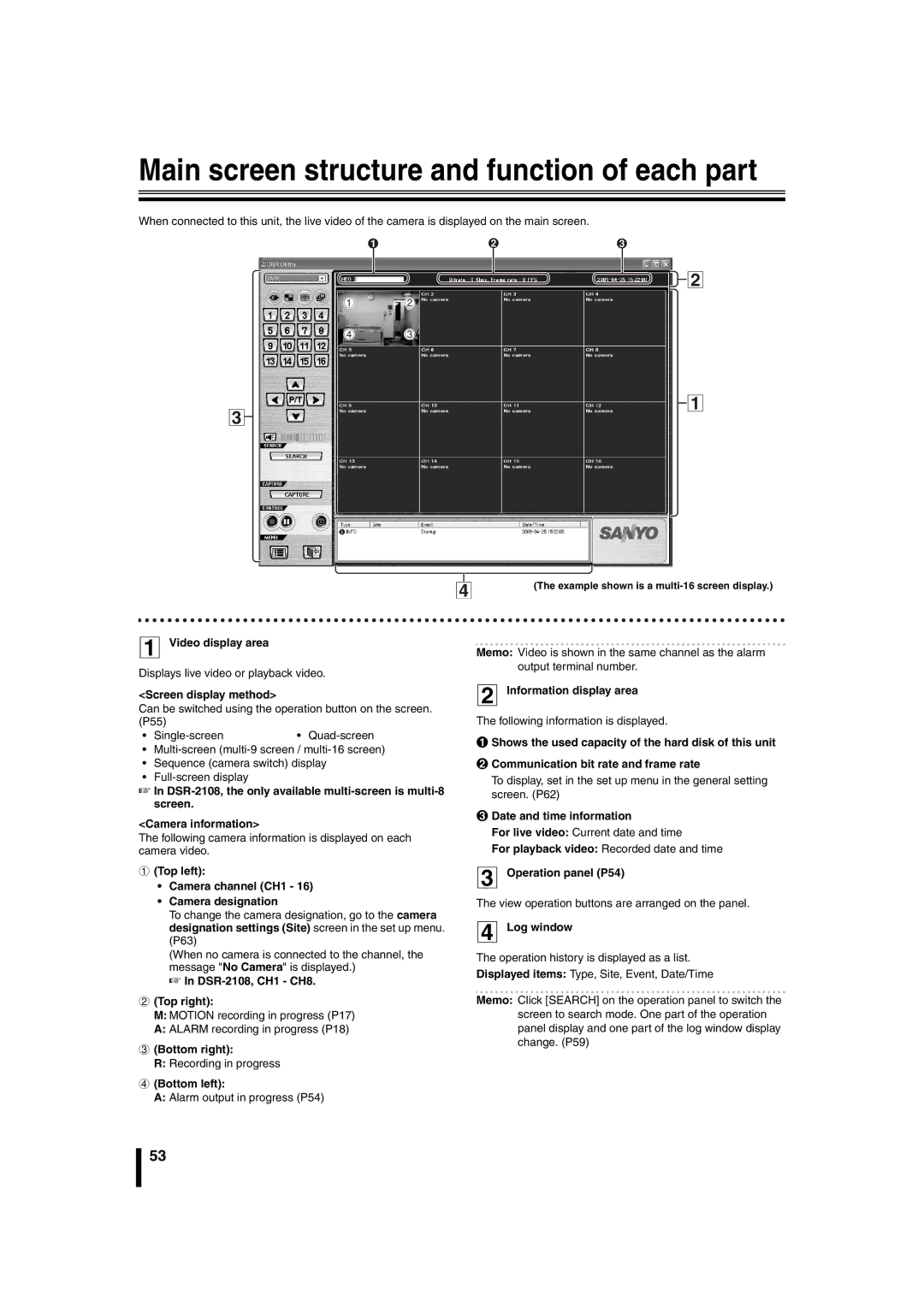
Main screen structure and function of each part
Main screen structure and function of each part
Switching the display mode of the screen
Main screen basic operations
Multi-screen display
DSR-2108, the only available multi-screen is multi-8 screen
BSequence camera switch display
BSwitching recording functions
Main screen basic operations
Recording live video BRecording method
Freezing the live video
Audio is output
Saving images
Sets the menu using this unit
Operating the PTZ dome camera
BFor Pan/Tilt operations
BFor Zoom/Focus operations
Search mode operations
Start Point
END Point
Back UP
Search mode operations
Searching and playing recorded video
Backing up DVR recorded video
Setup menu settings
General settings General
Setup menu settings
Camera designation settings Site
BModify the registered content Modify
BRegistering the additional DVR Addition
Event settings Event
Event log search, view, save Log View
Record settings Record
Disk settings Disk
Version information About
Remote Setup
Remote Setup operating procedure
Clicking Cancel
Clicking Apply
Remote Setup
BCommon settings General BChannel-specific settings
OSD
Setting the Alarm-Set
BAlarm Out
BSetting an alarm input terminal
BSetting an alarm output terminal
Setting the Monitor2
If Sequence is set to OFF
If Sequence is set to on
Setting the Record
BResolution Common to all channels
BSetting the detection frame
BSetting the Schedule recording
Click the Timer Set button
Click or drag a grid cell in the desired detection frame
System settings
BSetting the System
BClock Set
S.T./SUMMER Time P10
Description
BPTZ Control
RS-485
Data Speed
Setting the Network
BDDNS settings
BNetwork settings
Setting the NTP
Setting the Storage
Return Mail Address
NTP USE
Operations using the Web browser
BFunctions of the main operation panel
Operations using the Web browser
BFunctions of the search operation panel
BSaving still images to the PC
BSaving moving videos to the PC
Click the Capture button
Select the Channel 2 to be saved Click the OK 3 button
Part names of the remote control
Specifications
BDimensions unit mm
Dimensions of DSR-2116 and DSR-2108 are the same
BDVR ID input display list
Mounting the hard disk S-ATA
HDD 1 HDD
Memo
Memo
Memo
L8HBT, L8HBU/XE, US 0609KP-LD