Outdooe Units
„ R410A Models Indoor Units
Page
Check of Density Limit
Contents
Test RUN
Contents
Preparing for Test Run
Test Run
Items to Check Before the Test Run
Test Run Procedure
Main Outdoor Unit PCB Setting
Setting of Unit Control PCB
Unit No. setting
Indoor unit setting S004 Rotary switch, red
System address S003 System address No P DIP switch, blue 10
No. of outdoor units Outdoor unit setting S006
Automatic Address Setting from the Outdoor Unit
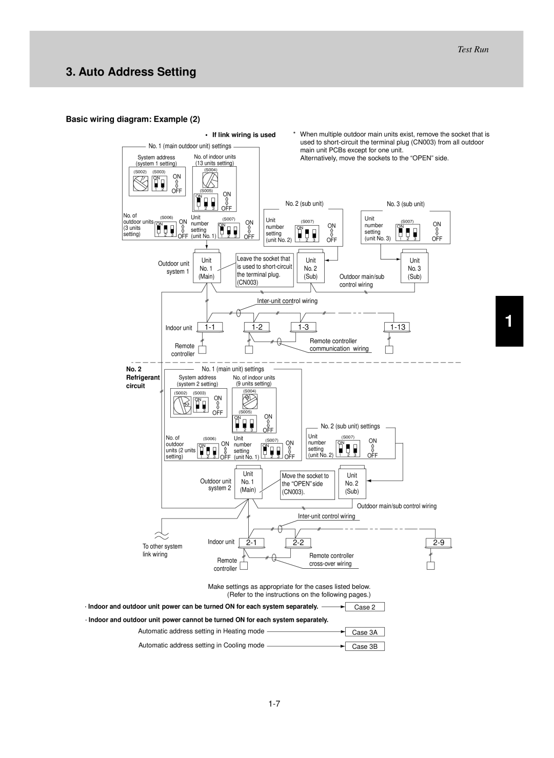
Auto Address Setting
Auto Address Setting Basic wiring diagram Example
Circuit
22-9
Refrigerant
Units
Case 2 Automatic Address Setting no compressor operation
Automatic Address Setting from Outdoor Unit
On the No
Case 3A Automatic Address Setting in Heating Mode
Case 3B Automatic Address Setting in Cooling Mode
Automatic Address Setting* from the Remote Controller
On outdoor main unit PCB
Display during automatic address setting
Remote controller display
Use the remote controller to check the indoor unit address
Auto Address Setting Remote Controller Test Run Settings
If 1 indoor unit is connected to 1 remote controller
Remote Controller Test Run Settings
Test Run
Possible cause of malfunction
Meaning of Alarm Messages
Alarm contents
P02
Alarm messages displayed on system controller
Main Operating Functions
Wireless Remote Controller
Timer Remote Controller RCS-TM80BG
Deg
Room Temperature Control
Main Operating Functions
Thermostat is turned ON/OFF according to as shown below
After the compressor turns on
Operating mode change Shifted set temp
FAN Speed selector button
Wireless Remote Controller
Mode button
Transmitter
C Sensor button
Cool mode and Dry mode, if the flaps are set in a downward
Filter button
Address button
OFF Cycle Timer
Indicator when swing operation is stopped
Timer SET button
OFF Timer
Receiver
Control
Temperature sensors at the indoor unit side are used
Operation
Multiple units Group
Cover
Using the Wireless Remote Control Unit
How to install batteries
Address Settings
D type
Type
Control unit will not be accepted
Emergency Operation
Operation
Shutdown
Press the Emergency operation button once more
Trouble Possible Cause
Troubleshooting
Trouble Possible Cause Remedy
How to Use the Timer Remote Controller Operating buttons
Timer Remote Controller RCS-TM80BG
Names and Operations
Timer OFF indication
Display Section Refer to Setting indication
Timer No. indication
Timer program
How to install the Remote Controller
Installation Manual for Timer Remote Controller
To Display the Sensor Temperature
Group Control Using 2 Remote Controllers
Remote Controller Setting Mode
Indoor Unit Setting Mode
13/32
Press To change the present hour in the range of 0 to 23
Setting the Present Time
Once you enter in the setting mode Day and time fl ash
Set to today’s day of the week
Select a Timer number
Weekly Program Function Checking Weekly Timer
Program image diagram
Press To enter the program confirmation mode Start setting
Set the minute. program step
Set the hour. program step
Indoor unit starts operation at the programmed time
Press / to change the temperature setting
Set the program pattern. program step
Pattern
Deleting the Program Timer
How to invalidate the program timer
How to cancel the program timer invalidation
If Power Failure Occurred
Before Asking Repair Work
Duplicating the Program Timer
You can duplicate the preset program by day
Select the copy source
Outing Function
Precautions
„ For Example Setting at Outing Temperature 86F 30C
Room temperature
Outing function indication Status
Canceling the outing function
Outing function indication
Sleeping Function
Wired Remote Controller Test Run Settings
Simple Settings Function
Procedure
List of Simple Setting Items
Detailed Settings Functions
Description
List of Detailed Setting Items
Setting data
Item code Setting data Description
Code Description
Setting data
Timer Remote Controller RCS-TM80BG
Table of DC Fan Motor Tap Settings ceiling-mounted type
TP6 TP3 TP1
Maintained
Remote Controller Servicing Functions
Display Sensor Servicing check Alarm history Press and hold
Test Run Function
Normal remote controller display
Trouble Diagnosis
Contents of Remote Controller Switch Alarm Display
Heat exchanger 1 gas temp. sensor F06
Display meaning
Are occurring Automatic address setting is in progress
Number that was set Alarm display
OFF
Alarm code Alarm meaning
2WAY ECO-i Alarm Codes
E15 Alarm Alarm code
E06 Alaral rm Alarm code
Alarm E04 occurs
E12 Alarm Alarm code
At a number of indoor units
E16 Alarm Alarm code
E20 Alarm Alarm code
E24 Alarm Alarm code
Power at the outdoor unit main is turned OFF
E25 Alarm Alarm code
E26 Alarm Alarm code
E29 Alarm Alarm code
Outdoor unit control PCB
F04, F05, F22 Alarm Alarm code
Crossed wiring or installation error
Check Check for crossed wiring and installation errors
Alarm meaning
Identification of the problem in this case
F06, F23 Alarm Alarm code
F07, F24 Alarm Alarm code
F08
Alarm code F12
F16 Alarm Alarm code
F17 Alarm Alarm code
H03 alarm Alarm code
F31 Alarm Alarm code
Valve must be replaced
H06 Alarm Alarm code
On the degree of the problem
Which may damage the compressor
H11, H12, H21, H22 Alarm Alarm code
H05, H15, H25 Alarm Alarm code
H13, H23 Alarm Alarm code
L05 Alarm Alarm code
H31 Alarm Alarm code
L04 Alarm Alarm code
L18 alarm Alarm code
L06 Alarm Alarm code
L10 Alarm Alarm code
L17 Alarm Alarm code
P03, P17, P18 Alarm Alarm code
P04 Alarm Alarm code
Noise in some cases
P05 Alarm Alarm code
P16 Alarm Alarm code
Primary or secondary current
P29 Alarm Alarm code
P22 Alarm Alarm code
P26 Alarm Alarm code
Compressor magnet SW seizing detection
Blinking inspection display 1 Automatic backup
Alarm code Blinking Inspection display
Corresponding outdoor unit
Alarm meaning Compressor magnet SW seizing detected
Alarm may be caused by the effects of noise. See notes
Within that refrigerant tubing system are stopped
Page
PCB and Functions
Outdoor Unit Control PCB CR-CHDX14053
Outdoor Unit Control PCB
Functions for CR-CHDX14053
Progress will stop the automatic address setting operation
Outdoor Unit Control PCB
Mode. Static signal
System only
Link wiring
Setting the Outdoor Unit address S007 Setting Address
JP1
Indoor Unit Control PCB
T10
For DC Fan Motor CR-SXRP56B-B
For AC Fan Motor CR-UXRP71B-B
CR1 for CR-KR74GXH56A/KHX0752~KHX1852 Wall-Mounted
CR1 for CR-KR254GXH56A/KHX2452 Wall-Mounted
CR2 for POW-KR74GXH56/KHX0752~KHX2452 Wall-Mounted
CN017
Signal. Jumper wire cut Static signal continuous signal
Or less
CN014
Option
SELF-DIAGNOSIS Function Table
Trouble Cause and correction
Alarm displayAlarm description
Self-Diagnosis Function Table
Self-Diagnosis Function Table
Cause
Check items E15 E16 E20
DISCH2
Alarm code Alarm meaning
Service Checker
Functions Functions on the ordinary display
Outdoor Unit Maintenance Remote Controller
System Diagram
All units test run Fig
Temperature monitor
All units start/stop Fig
Cooling/heating change Fig
Item code Remarks
Display functions
Item codes can be changed with Buttons
Sample display -4, Fig
XX-YY R.C
Sample Display A, B
Outdoor unit
Monitoring Operations
Display of unit No main unit
Indoor unit
Outdoor Unit Alarm History Monitor
Code Parameter Description SET Data
„ Setting mode
Parameter Description SET Data
„ Setting mode
Page
200706MDC