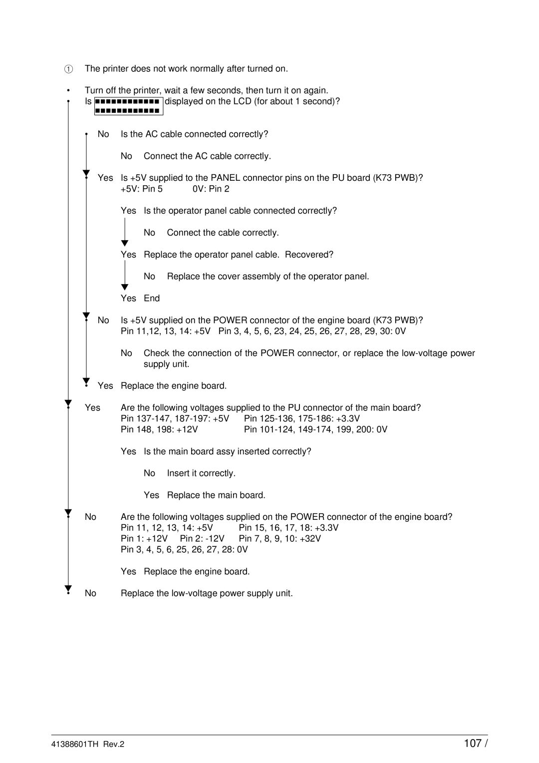
1The printer does not work normally after turned on.
•Turn off the printer, wait a few seconds, then turn it on again.
• Is ![]()
![]()
![]()
![]()
![]()
![]()
![]()
![]()
![]()
![]()
![]()
![]()
![]()
![]()
![]()
![]()
![]()
![]()
![]()
![]()
![]()
![]()
![]()
![]()
![]()
![]() displayed on the LCD (for about 1 second)?
displayed on the LCD (for about 1 second)?
• | No | Is the AC cable connected correctly? | ||
|
| No | Connect the AC cable correctly. | |
▼ | Yes | Is +5V supplied to the PANEL connector pins on the PU board (K73 PWB)? | ||
• | ||||
|
| +5V: Pin 5 | 0V: Pin 2 | |
|
| Yes | Is the operator panel cable connected correctly? | |
|
|
| No | Connect the cable correctly. |
|
| ▼ |
|
|
|
| Yes | Replace the operator panel cable. Recovered? | |
|
|
| No | Replace the cover assembly of the operator panel. |
|
| ▼ |
|
|
|
| Yes | End |
|
▼ | No | Is +5V supplied on the POWER connector of the engine board (K73 PWB)? | ||
• | ||||
|
| Pin 11,12, 13, 14: +5V Pin 3, 4, 5, 6, 23, 24, 25, 26, 27, 28, 29, 30: 0V | ||
▼
• Yes
▼
• Yes
No Check the connection of the POWER connector, or replace the
Replace the engine board.
Are the following voltages supplied to the PU connector of the main board?
Pin | Pin | +3.3V | |
Pin 148, 198: +12V | Pin | 199, 200: 0V |
|
| Yes Is the main board assy inserted correctly? | ||
|
| No | Insert it correctly. |
|
|
| Yes | Replace the main board. | |
▼ | No | Are the following voltages supplied on the POWER connector of the engine board? | ||
• | ||||
|
| Pin 11, 12, 13, 14: +5V | Pin 15, 16, 17, 18: +3.3V | |
|
| Pin 1: +12V Pin 2: | Pin 7, 8, 9, 10: +32V | |
|
| Pin 3, 4, 5, 6, 25, 26, 27, 28: 0V | ||
|
| Yes Replace the engine board. | ||
▼ | No | Replace the | ||
• | ||||
41388601TH Rev.2 | 107 / |
