41388601TH Rev.2
133 /
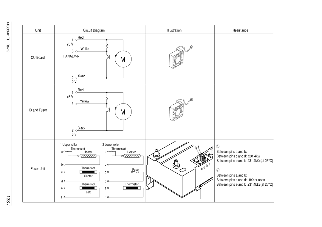
Unit |
| Circuit Diagram |
| Illustration | Resistance |
| |
| 1 | Red |
|
|
|
|
|
|
|
|
|
|
|
| |
| +5 V |
|
|
|
|
|
|
| 3 | White |
|
|
|
|
|
|
|
|
|
|
|
| |
CU Board |
| M |
|
|
| ||
|
|
|
|
|
| ||
|
|
|
|
|
|
| |
| 2 | Black |
|
|
|
|
|
|
|
|
|
|
|
| |
| 0 V |
|
|
|
|
|
|
| 1 | Red |
|
|
|
|
|
|
|
|
|
|
|
| |
| +5 V |
|
|
|
|
|
|
| 3 | Yellow |
|
|
|
|
|
|
|
|
|
|
|
| |
ID and Fuser |
|
|
| M |
|
|
|
|
|
|
|
|
|
| |
| 2 | Black |
|
|
|
|
|
|
|
|
|
|
|
| |
| 0 V |
|
|
|
|
|
|
1 Upper roller |
| 2 Lower roller | b a | 1 |
| ||
| Thermostat |
| Thermostat |
| |||
a | a | Between pins a and b: |
| ||||
| Heater | Heater |
|
| |||
|
|
|
|
|
| Between pins c and d: 231.4kΩ |
|
|
|
|
|
|
| Between pins e and f: 231.4kΩ | (at 25° C) |
b |
| Thermistor | b |
| c d | e f |
|
Fuser Unit |
| c | Fuse | 2 |
| ||
c |
|
|
|
| Between pins a and b: |
| |
|
| Center |
|
|
|
| |
d |
|
| d |
|
| Between pins c and d: 0Ω or open | |
| Thermistor | Thermistor |
| Ω | ° | ||
|
|
|
| ||||
e |
|
| e |
|
| Between pins e and f: 231.4k | (at 25 C) |
|
|
|
|
|
| ||
|
| Left |
|
|
|
|
|
f |
|
| f |
|
|
|
|