(5)Driving and Up-and-Down Movements of I/D Unit
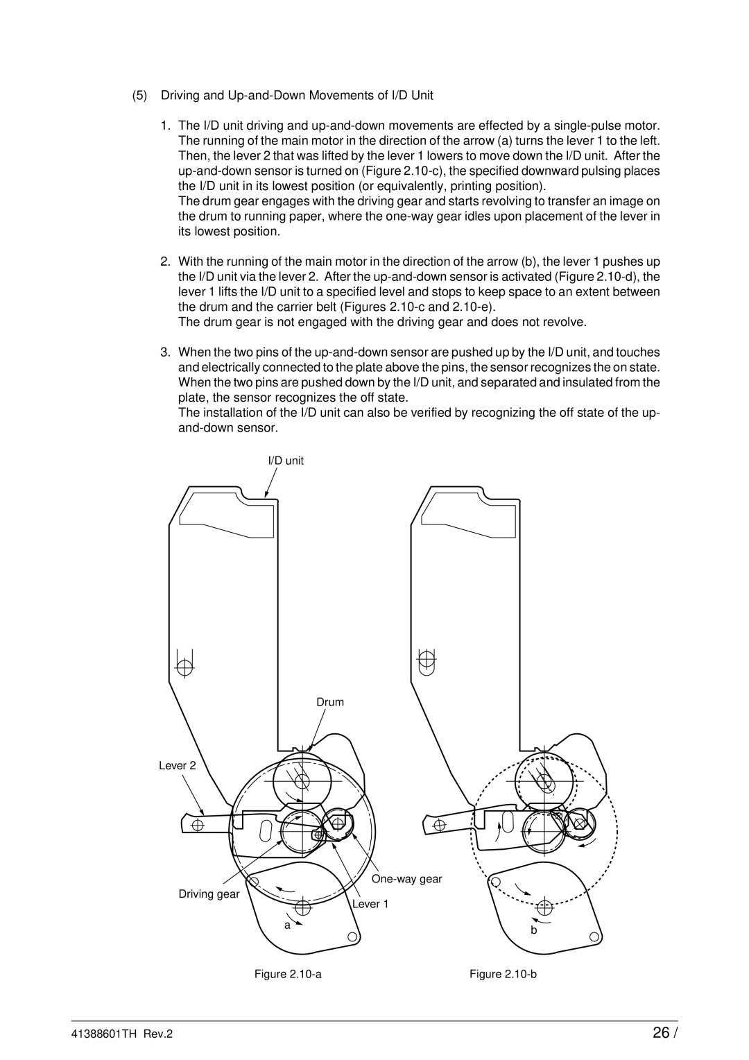
1.The I/D unit driving and up-and-down movements are effected by a single-pulse motor. The running of the main motor in the direction of the arrow (a) turns the lever 1 to the left. Then, the lever 2 that was lifted by the lever 1 lowers to move down the I/D unit. After the up-and-down sensor is turned on (Figure 2.10-c), the specified downward pulsing places the I/D unit in its lowest position (or equivalently, printing position).
The drum gear engages with the driving gear and starts revolving to transfer an image on the drum to running paper, where the one-way gear idles upon placement of the lever in its lowest position.
2.With the running of the main motor in the direction of the arrow (b), the lever 1 pushes up the I/D unit via the lever 2. After the up-and-down sensor is activated (Figure 2.10-d), the lever 1 lifts the I/D unit to a specified level and stops to keep space to an extent between the drum and the carrier belt (Figures 2.10-c and 2.10-e).
The drum gear is not engaged with the driving gear and does not revolve.
3.When the two pins of the up-and-down sensor are pushed up by the I/D unit, and touches and electrically connected to the plate above the pins, the sensor recognizes the on state. When the two pins are pushed down by the I/D unit, and separated and insulated from the plate, the sensor recognizes the off state.
The installation of the I/D unit can also be verified by recognizing the off state of the up- and-down sensor.
I/D unit
Drum
Lever 2
| One-way gear |
Driving gear | Lever 1 |
|
a | b |
|
Figure 2.10-a | Figure 2.10-b |

