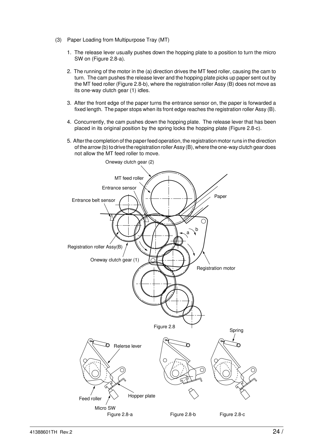
(3)Paper Loading from Multipurpose Tray (MT)
1.The release lever usually pushes down the hopping plate to a position to turn the micro SW on (Figure
2.The running of the motor in the (a) direction drives the MT feed roller, causing the cam to turn. The cam pushes the release lever and the hopping plate picks up paper sent out by the MT feed roller (Figure
3.After the front edge of the paper turns the entrance sensor on, the paper is forwarded a fixed length. The paper stops when its front edge reaches the registration roller Assy (B).
4.Concurrently, the cam pushes down the hopping plate. The release lever that has been placed in its original position by the spring locks the hopping plate (Figure
5.After the completion of the paper feed operation, the registration motor runs in the direction of the arrow (b) to drive the registration roller Assy (B), where the
Oneway clutch gear (2)
MT feed roller
Entrance sensor
Paper
Entrance belt sensor
b a ![]()
Registration roller Assy(B)
Oneway clutch gear (1)
Registration motor
Figure 2.8
Spring
Relerse lever
Feed roller | Hopper plate |
|
|
|
|
| |
Micro SW |
|
| |
| Figure | Figure | Figure |
41388601TH Rev.2 | 24 / |