41388601TH Rev.2
129 /
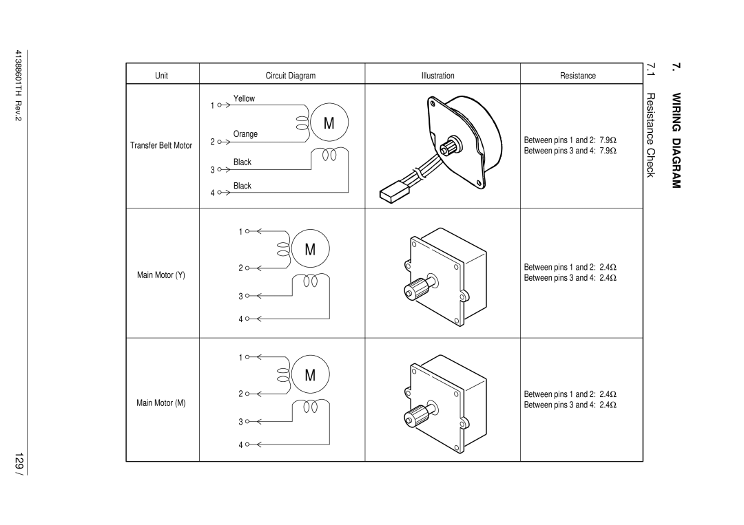
Unit | Circuit Diagram | Illustration | Resistance |
| Yellow |
|
|
| 1 |
|
|
| Orange | M |
|
|
| Between pins 1 and 2: 7.9Ω | |
Transfer Belt Motor | 2 |
| |
|
| Between pins 3 and 4: 7.9Ω | |
|
|
| |
| Black |
|
|
| 3 |
|
|
| Black |
|
|
| 4 |
|
|
| 1 |
|
|
| M |
|
|
Main Motor (Y) | 2 |
| Between pins 1 and 2: 2.4Ω |
|
| Between pins 3 and 4: 2.4Ω | |
| 3 |
|
|
| 4 |
|
|
| 1 |
|
|
| M |
|
|
Main Motor (M) | 2 |
| Between pins 1 and 2: 2.4Ω |
|
| Between pins 3 and 4: 2.4Ω | |
| 3 |
|
|
| 4 |
|
|
7. | 7. |
1 |
|
Resistance Check | WIRING DIAGRAM |