LC24-20MULTI-FONT
Trademark Acknowledgements
HOW to USE this Manual
Reference
Table of Contents
Default SETTINGS-EDS Mode
Index
Page
Chapter
Printer Components
Component Description
Feature
Summary of Printer Features
Character spacing LCD Control panel Font/Pitch Lock
FC-2Z OCR-B OCR-A Code UPC/EAN
Font Style Example
Quad-s i z MI
Memo
Printer Placement
Setting UP the Printer
Unpacking and Inspection
Page
Installing the platen knob
Setting UP
Front cover can stay on the printer
Removing the front cover
Installing the ribbon cariridge
Installing the ribbon cartridge
Make sure that the ribbon is positioned correctly
Installing the front cover
Installing the mute cover
Installing the paper guide
12. Connecting the interface cable
Connecting the interface cable
Configuring your software for the printer
Selection of Paper
Paper Installation and USE
Shows the recommended print area for each type of papers
Location of the adjustment lever
Adjusting the Printing GAP
Paper path for fanfold forms
Loading Fanfold Forms
Opening the mute cover and correct lever position
Loading the paper
Tractor cover Mamp’ever
Mute cover
10.Tear off the printed fanfold paper
Paper parking
Tear off function
Paper unparking
11.Paper path for cut forms
Loading Single Sheets
13.Place a single sheet between the guides
14.Pull the bail lever forward to load paper
‘ONT‘lTCHn n mm
Button and Indicator Function
On Line
EJECT/PARK
Font
Short test mode
POWER-UP Functions
Long self-test
Long test mode
Font and Pitch lock mode
Print area test mode
Pitch lock mode
Font lock mode
Dot adjustment mode
DRAFT, Draft Cond and BIT Image
Hexadecimal dump
Top of form
Switch Combination Functions
Changing the auto loading position
Forward micro-feed
Reverse micro-feed
Save Macro Definition
Clearing the buffer/All reset
Page
Summary of display messages
Conditions Indicated by Messages and Tones
Macro
Summary of beep tones
Page
HOW to SET the EDS Mode
Default SETTINGS-EDS Mode
OFF
Functions of the EDS Settings
Switch A-1 Emulation
Switch B-2 Paper-out
Switches C-3 to C-5 Page Length
Switches E-1 to E-5 LQ Font Selection
Page
Page
Troubleshooting
Troubleshooting
Page
Page
Page
Move the lever to a lighter setting front. See Chapter
Page
Page
Maintenance
Automatic Sheet Feeder SF-1ODS
Optional Accessories
Remove the front cover, and open the rear cover
Setting up
Printer
Insert the stacker attachment
Loading paper
Fan the paper before inserfing into the ASF
10.Push the paper loading lever to hold the paper stack
Feeding a single sheet
Pull Tractor Unit PT-IOZS
Printer co
Tractor covel
Clamp lever Tractor cover
Font Name
Font Cartridges and RAM Cartridges
Install the connector cover into the printer
Close the front cover
Interface Converter SPC-8K
21.Connect the Parallel connector to the printer
Transfer speed
DIP Switch Functions on The Converter
Page
Printer Control Commands
Select LQ font
Font Control Commands
Select print quality
Emphasized printing
Cancel emphasized printing
Select italic characters
Select upright characters
Overlining
Cancel double-strike printing
Double-strike printing
Underlining
Superscript
Select score
Select ornament character
Subscript
Cancel superscript or subscript
Select character set #l
Character SET Commands
Select standard character set
Select IBM character set
Select IBM code
Select international character set
Select normal zero
Enable printing of all character codes
Enable printing of all character codes on next character
Select slash zero
Semi-condensed pitch
Character Size and Pitch Commands
Pica pitch
Elite pitch
Select font and pitch
Cancel condensed printing
Proportional spacing
Expanded printing for one line
Cancel one-line expanded printing
Expanded printing
Increase character spacing
Select master print mode
Select character width
Return to normal height
Select double or quadruple size
Print double-height characters
Select character height, width, and line spacing
Set line spacing to 1/6 inch
Vertical Position
Set line spacing to 1/8 inch
Set line spacing to 7/60 or 7/72 inch
Set line spacing to n160inch or n172inch
Set base unitfor line spacing
Setline spacing to nl180 inch, n1216inch, or n1360inch
Line feed
Select forward feed mode
Select reverse feed mode
Execute &SC a
Set top of page at current position
Perform one n/180-inch, n/216-inch, or n/360-inch line feed
Perform one nl180-inch reverse line feed
Feed paper n lines
Set bottom margin
Cancel bottom margin
Set page length to n lines
Set page length to n inches
Return to top of current
Disable paper-out detector
Enable paper-out detector
Form feed
Select vertical tab channel
Set vertical tab stops
Set vertical tab stops every n lines
Set vertical tab stops in channel
Vertical tab
Set right margin
Horizontal Position Commands
Set left margin
Set automatic line feed
Cancel automatic line feed
Set left and right margins
Carriage return
Full justify
Left just$y
Center text
Right justify
Relative horizontal tab
Reset all tab stops
Set horizontal tab stop every n columns
Horizontal tab
Absolute-horizontal tab in columns
Relative horizontal tab in inches
Absolute horizontal tab in inches
Print double-density, double-speed 8-bit graphics
Graphics Commands
Print normal-density 8-bit graphics
Print double-density 8-bit graphics
Print hex-density 24-bit graphics
Print quadruple-density 8-bit graphics
III, n2, ml, m2
Select graphics mode
Convert graphics density
Define download characters
Download Character Commands
Decimal Hexadecimal ESC = ~ #
Copy character set from ROM into RAM
Select ROM character set
Select download character set
Shift download character area
Other Printer Commands
Bell
Set printer off-line
Set printer on-line
Stop printing
Auto feed
Uni-directional printing
One-line uni-directional printing
Manual feed
Set initial conditions
Reset printer
Set print start position on ASF
Download Characters
Defining Your OWN Characters with Standard Mode
122
Assigning the character data
Assigning a value of character space
Telephone symbol wtth normal LQplca
1250
Sample program
Diffusion Ranges of Cars & Telephones
Assigning the download character set
Defining Your OWN Characters with IBM Mode
Assigning the character dot pattern
Telephone symbol with LQ pica
10100.00,00
Assigning the Index Table data
130
131
132
MS-DOS and Your Printer
Programming the Printer with DOS Commands
ESC
Aedlin LQELITE.DAT
1310 1320
Programming with Basic
137
138
139
140
How the program works
142
Reference
Specifications
32X
Friction or push tractor feed standard
Film ribbon cartridgeFZ24
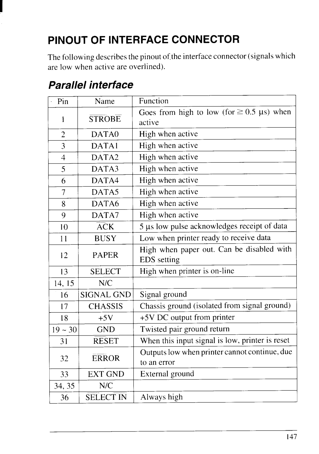
Parallel interface
Pinout of Interface Connector
10 N/C
Serial Interface
II-3 F9
Standard character set #2
151
Korea Irish Legal
International character sets
Code Page #437 U. S.A
IBM character set #2
154
Code Page #850 Multi-1ingual
Code Page #860 Portuguese
Code Page #861 Icelandic
Code Page #863 Canadian French
Code Page #865 Nordic
1 m
Character set #1
Page
Std #437 #850 #860 #861 #863 #865 HperlSulIBM Lmal
Proportional Spacing Table
24 24 24 24 24
Chr Proportionalwidth Std #437 #850 #860 #861 #863 #865
Std #437 #850 #860 #861 #863 #865
Chr
140
197 198 199
200
INT
181 134 164 182 143 132 183 145 142 184 198 199 207
+--l-+
Index
Fanfold forms, loading, Z-27
Off line command, I I g On Line button
Page
Standard Mode
Command Summary
Xx ’
179
Following commands take effect with the IBM mode
IBM Mode
181
Consumer Response
11111
Bail Lever Functions