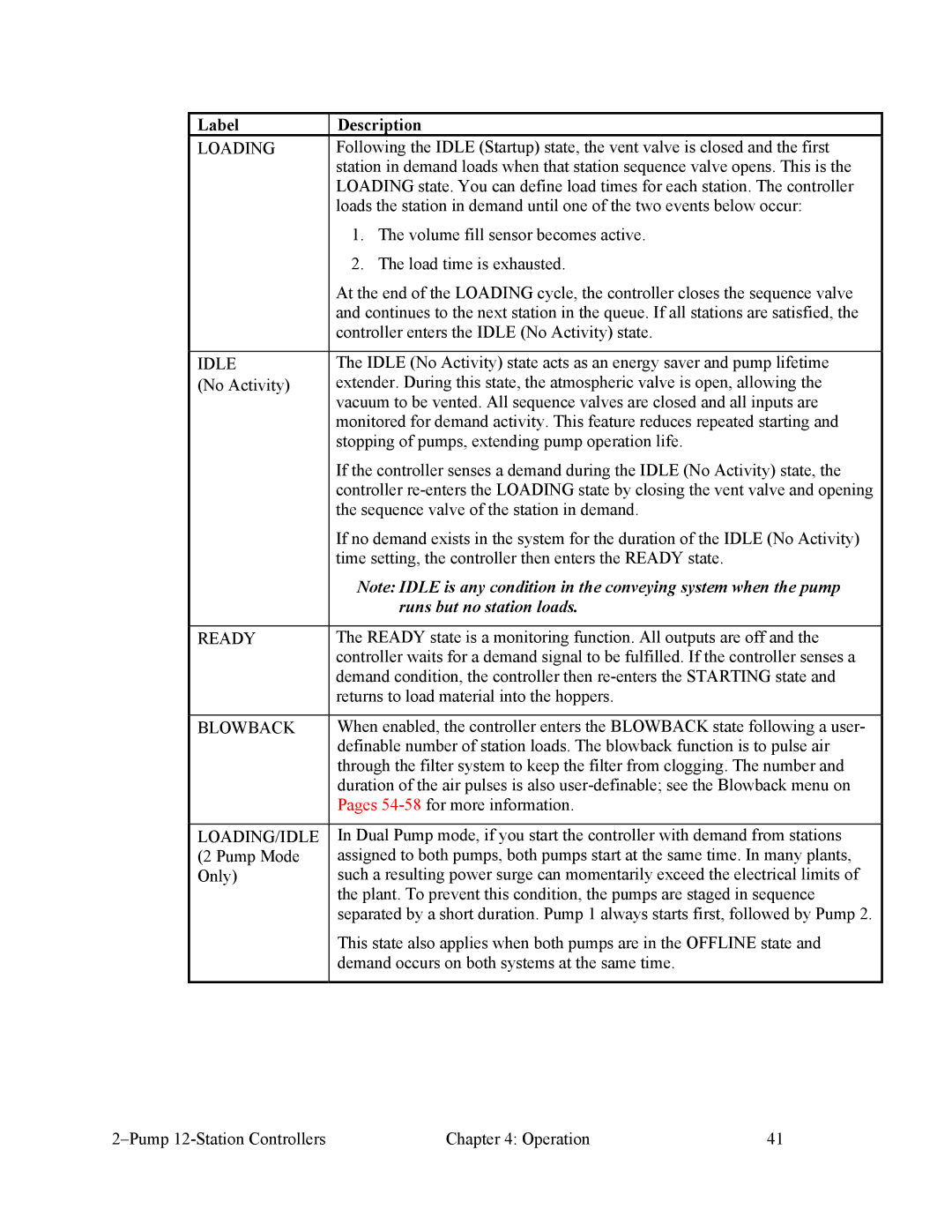
Label | Description |
LOADING | Following the IDLE (Startup) state, the vent valve is closed and the first |
| station in demand loads when that station sequence valve opens. This is the |
| LOADING state. You can define load times for each station. The controller |
| loads the station in demand until one of the two events below occur: |
| 1. The volume fill sensor becomes active. |
| 2. The load time is exhausted. |
| At the end of the LOADING cycle, the controller closes the sequence valve |
| and continues to the next station in the queue. If all stations are satisfied, the |
| controller enters the IDLE (No Activity) state. |
|
|
IDLE | The IDLE (No Activity) state acts as an energy saver and pump lifetime |
(No Activity) | extender. During this state, the atmospheric valve is open, allowing the |
| vacuum to be vented. All sequence valves are closed and all inputs are |
| monitored for demand activity. This feature reduces repeated starting and |
| stopping of pumps, extending pump operation life. |
| If the controller senses a demand during the IDLE (No Activity) state, the |
| controller |
| the sequence valve of the station in demand. |
| If no demand exists in the system for the duration of the IDLE (No Activity) |
| time setting, the controller then enters the READY state. |
| Note: IDLE is any condition in the conveying system when the pump |
| runs but no station loads. |
|
|
READY | The READY state is a monitoring function. All outputs are off and the |
| controller waits for a demand signal to be fulfilled. If the controller senses a |
| demand condition, the controller then |
| returns to load material into the hoppers. |
|
|
BLOWBACK | When enabled, the controller enters the BLOWBACK state following a user- |
| definable number of station loads. The blowback function is to pulse air |
| through the filter system to keep the filter from clogging. The number and |
| duration of the air pulses is also |
| Pages |
|
|
LOADING/IDLE | In Dual Pump mode, if you start the controller with demand from stations |
(2 Pump Mode | assigned to both pumps, both pumps start at the same time. In many plants, |
Only) | such a resulting power surge can momentarily exceed the electrical limits of |
| the plant. To prevent this condition, the pumps are staged in sequence |
| separated by a short duration. Pump 1 always starts first, followed by Pump 2. |
| This state also applies when both pumps are in the OFFLINE state and |
| demand occurs on both systems at the same time. |
|
|
Chapter 4: Operation | 41 |
