SSPET5
2.3.1. Installation of the “flap switch” signal line
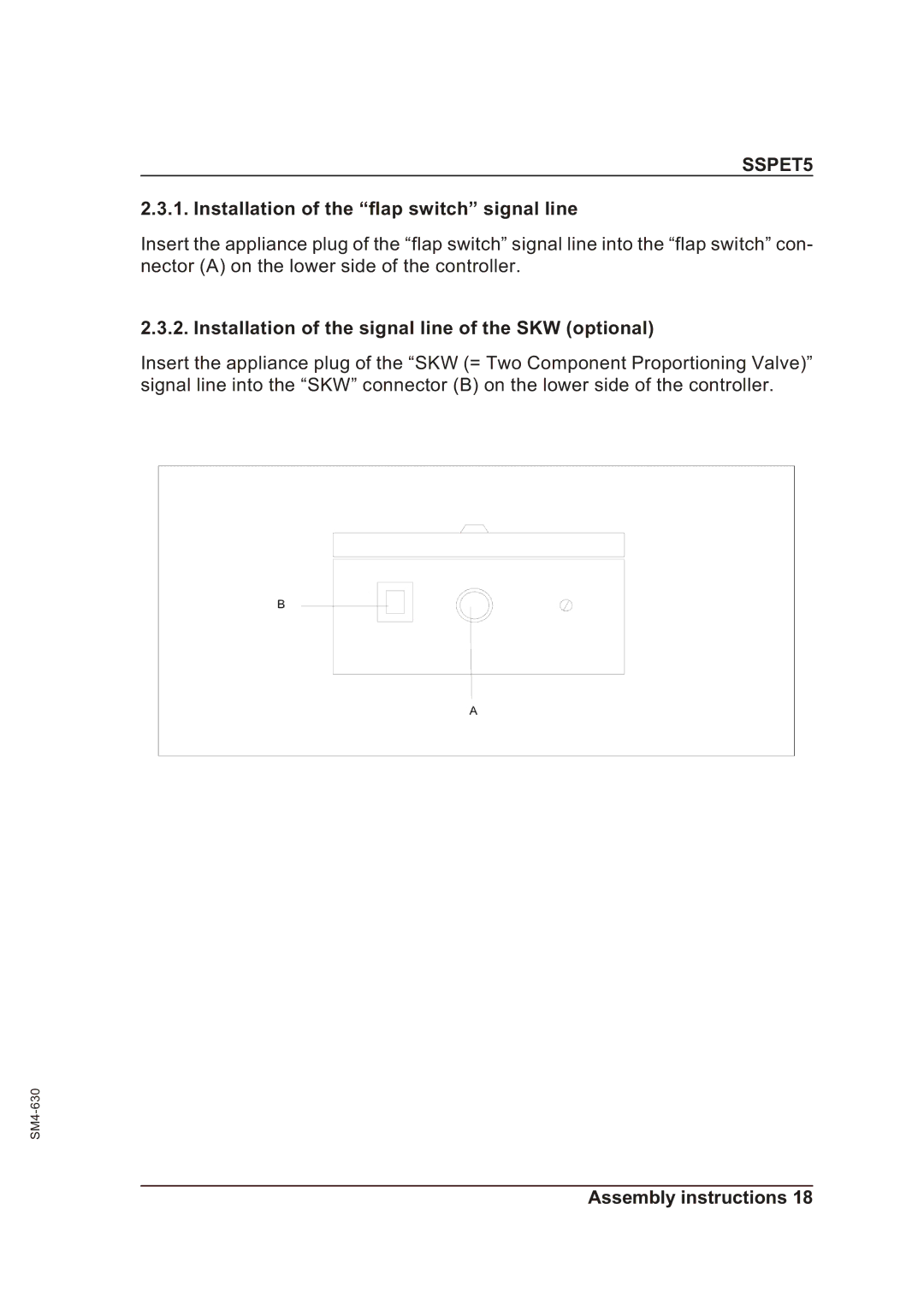
Insert the appliance plug of the “flap switch” signal line into the “flap switch” con- nector (A) on the lower side of the controller.
2.3.2. Installation of the signal line of the SKW (optional)
Insert the appliance plug of the “SKW (= Two Component Proportioning Valve)” signal line into the “SKW” connector (B) on the lower side of the controller.
