Manuals
/
Brands
/
TV and Video
/
Home Theater Server
/
SUPER MICRO Computer
/
TV and Video
/
Home Theater Server
SUPER MICRO Computer
6014P-8, 6014P-82, 6014P-82R, 6014P-8R
- page 115
1
115
126
126
Download
126 pages, 6.4 Mb
Appendix B: Software Installation
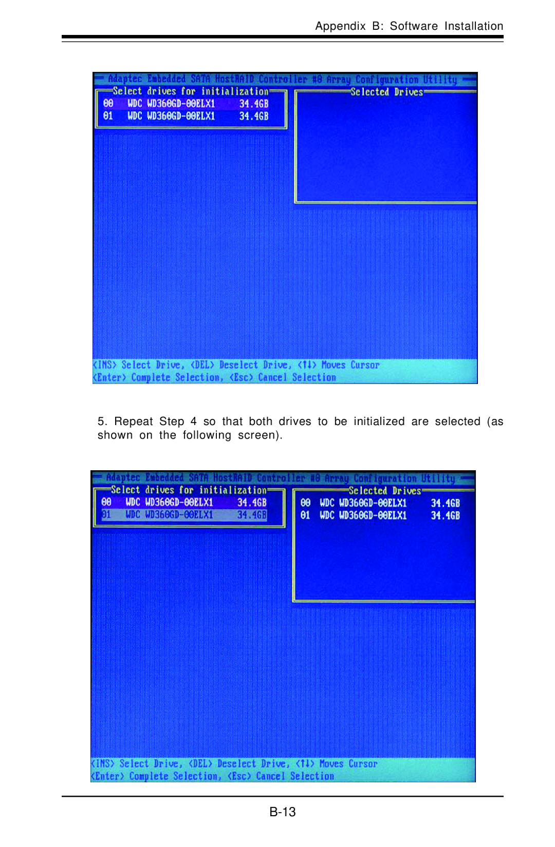
B-13
5. Repeat Step 4 so that both drives to be initialized are selected (as
shown on the following screen).
Contents
Main
SUPER
Printed in the United States of America
iii
Preface
About This Manual
Manual Organization
Chapter 1: Introduction
Chapter 2: Server Installation
Page
Page
vi
S UPER S
Table of Contents
Preface
Chapter 1: Introduction
Chapter 2: Server Installation
Chapter 3: System Interface
Chapter 5: Advanced Serverboard Setup
vii
viii
S UPER S
Chapter 6: Advanced Chassis Setup
Chapter 7: BIOS
Page
Page
Chapter 1 Introduction
1-1 Overview
1-1
1-2
1-2 Serverboard Features
Processors
Memory
Onboard SCSI
Onboard Controllers/Ports
1-3 Server Chassis Features
System Power
SCSI Subsystem
Page
Page
1-4 Contacting Supermicro
Headquarters
Europe
Asia-Pacific
2-1
Chapter 2 Server Installation
2-1 Overview
2-2 Unpacking the System
2-3 Preparing for Setup
2-2
Warnings and Precautions!
Rack Precautions
Server Precautions
-
-
Rack Mounting Considerations
2-4
2-4 Installing the System into a Rack
Identifying the Rack Sections
Chassis Rails
2-5
Installing the Rack Rails
Installing the Server into the Rack
Page
2-8
2-5 Checking the Serverboard Setup
Page
2-10
2-6 Checking the Drive Bay Setup
3-1
Chapter 3 System Interface
3-1 Overview
3-2 Control Panel Buttons
3-3 Control Panel LEDs
3-4 SCSI Drive Carrier LEDs
Page
4-1
Chapter 4 System Safety
4-1 Electrical Safety Precautions
4-2
4-2 General Safety Precautions
4-3
4-3 ESD Precautions
4-4
4-4 Operating Precautions
OR
5-1
Chapter 5 Advanced Serverboard Setup
5-1 Handling the Serverboard
Precautions
Unpacking
5-2
5-2 Processor and Heatsink Installation
CPU Installation
5-3
Warning!
Heatsink Installation
5-4
Removing the Heatsink/CPU
5-5
5-3 Connecting Cables
Connecting Data Cables
Connecting Power Cables
5-6
Connecting the Control Panel
5-7
5-4 I/O Ports
5-5 Installing Memory
CAUTION
DIMM Installation (Figures 5-5a and 5-5b)
5-8
5-9
5-6 Adding PCI Cards
5-10
5-7 Serverboard Details
CPU2
CPU1
Controller
S
X6DHP-8G Quick Reference
Jumper Description Default Setting
Connector Description
5-12
Controller
S
CPU2
CPU1
PHX
E7520 North Bridge
X6DHP-8G2 Quick Reference
Jumper Description Default Setting
Connector Description
5-14
5-8 Connector Definitions
ATX Power Connector
Processor Power Connector
NMI Button
5-15
Overheat/Fan Fail LED
NIC1/2 LEDs
HDD LED
Power & PWR Fail LED
5-16
GLAN1/2 (Ethernet Ports)
Power Button
Chassis Intrusion
UID Button & UID LED
5-17
Fan Headers
Universal Serial Bus (USB0/1)
Front Panel Universal Serial Bus Headers
Serial Ports
5-18
Power LED/Speaker
Wake-On-Ring
ATX PS/2 Keyboard and PS/2 Mouse Ports
5-19
SMB
SMB Power Connector
5-20
GLAN Enable/Disable
5-9 Jumper Settings
Explanation of Jumpers
CMOS Clear
5-21
SCSI Controller Enable/ Disable
SCSI Termination Enable/ Disable
VGA Enable/Disable
DOC IDE Slot Bus Select (JP17/JP18)
5-22
Watch Dog
Memory Speed Select (X6DHP-8G only)
5-23
5-10 Onboard Indicators
GLAN LEDs
SCSI LEDs (DA1/DA2)
Unit Identifier
5-24
5-11 Floppy/Hard Disk and SCSI Drive Connections
Chapter 5: Advanced Serverboard Setup
5-25
Ultra320 SCSI Connectors
Page
6-1
Chapter 6 Advanced Chassis Setup
Tools Required
6-1 Static-Sensitive Devices
Precautions
6-2
6-2 Control Panel
6-3
6-3 System Fans
System Fan Failure
Replacing System Cooling Fans
6-4
6-4 Drive Bay Installation/Removal
Accessing the Drive Bays
6-5
SCSI Drive Installation
3b
3a 3b
6-6
6-7
DVD-ROM and Floppy Drive Installation
6-8
6-5 Power Supply
6014P-8R/6014P-82R
Power Supply Failure
Removing/Replacing the Power Supply
6-9
6014P-8/6014P-82
Power Supply Failure
Removing/Replacing the Power Supply
6-10
Reconfiguring the Power Supply
6-11
6-12
Page
Page
7-1
Chapter 7 BIOS
7-1 Introduction
Starting the Setup Utility
7-2
7-2 Running Setup
7-3 Main BIOS Setup
Page
Page
Page
Page
7-4 Advanced Setup
Page
7-9
Cache Base 0-512K
Cache Base 512K-640K
Cache Extended Memory
Page
Page
Page
Page
Page
Page
7-16
Hardware Monitor Logic CPU Temperature Threshold
7-17
7-5 Security
Page
7-6 Boot
7-7 Exit
Page
Recoverable POST Errors
Terminal POST Errors
Appendix A BIOS POST Codes
Page
Page
Page
Page
Page
B-1
Appendix B Software Installation
B-1 Adaptec Embedded SATA RAID Controller Driver
Serial ATA (SATA)
Configuring BIOS settings for the SATA RAID Functions
B-2
Adaptec Embedded SATA with HostRAID Controller Driver
B-3
Using the Array Configuration Utility (ACU)
Using the Adaptec RAID Configuration Utility (ARC)
Page
B-5
B-6
Creating Arrays
B-7
Assigning Array Properties
B-8
B-9
B-10
B-11
B-12
Initializing Disk Drives
To initialize drives:
Page
B-14
Rebuilding Arrays
B-15
Using the Disk Utilities
Page
B-17
B-2 Installing Intel's ICH5R Driver by Adaptec and Windows OS
B-18
B-3 Installing Other Software Programs and Drivers
Installing Other Drivers
Page
Page
Appendix C System Specifications
Page
C-3
PFC Power Supply (ratings apply to each module)
Operating Environment
Regulatory Compliance