SUPERSERVER
Power LED/Speaker
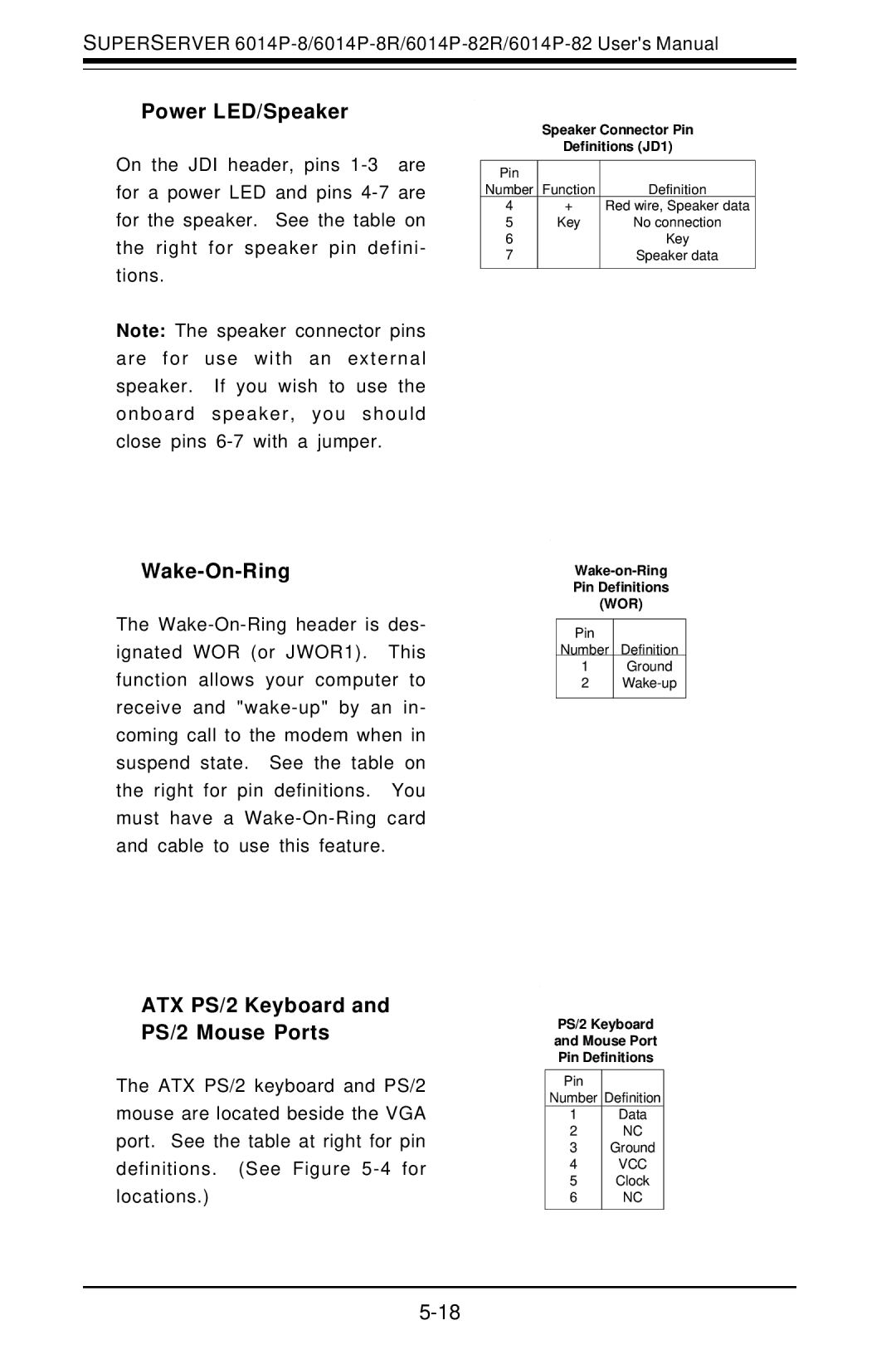
On the JDI header, pins
Note: The speaker connector pins are for use with an external speaker. If you wish to use the onboard speaker, you should close pins
Wake-On-Ring
The
ATX PS/2 Keyboard and PS/2 Mouse Ports
The ATX PS/2 keyboard and PS/2 mouse are located beside the VGA port. See the table at right for pin definitions. (See Figure
Speaker Connector Pin
Definitions (JD1)
Pin |
|
|
Number | Function | Definition |
4 | + | Red wire, Speaker data |
5 | Key | No connection |
6 |
| Key |
7 |
| Speaker data |
|
|
|
Pin Definitions
(WOR)
Pin
Number Definition
1Ground
2
PS/2 Keyboard
and Mouse Port
Pin Definitions
Pin
Number Definition
1Data
2NC
3Ground
4VCC
5Clock
6NC