SUPERSERVER
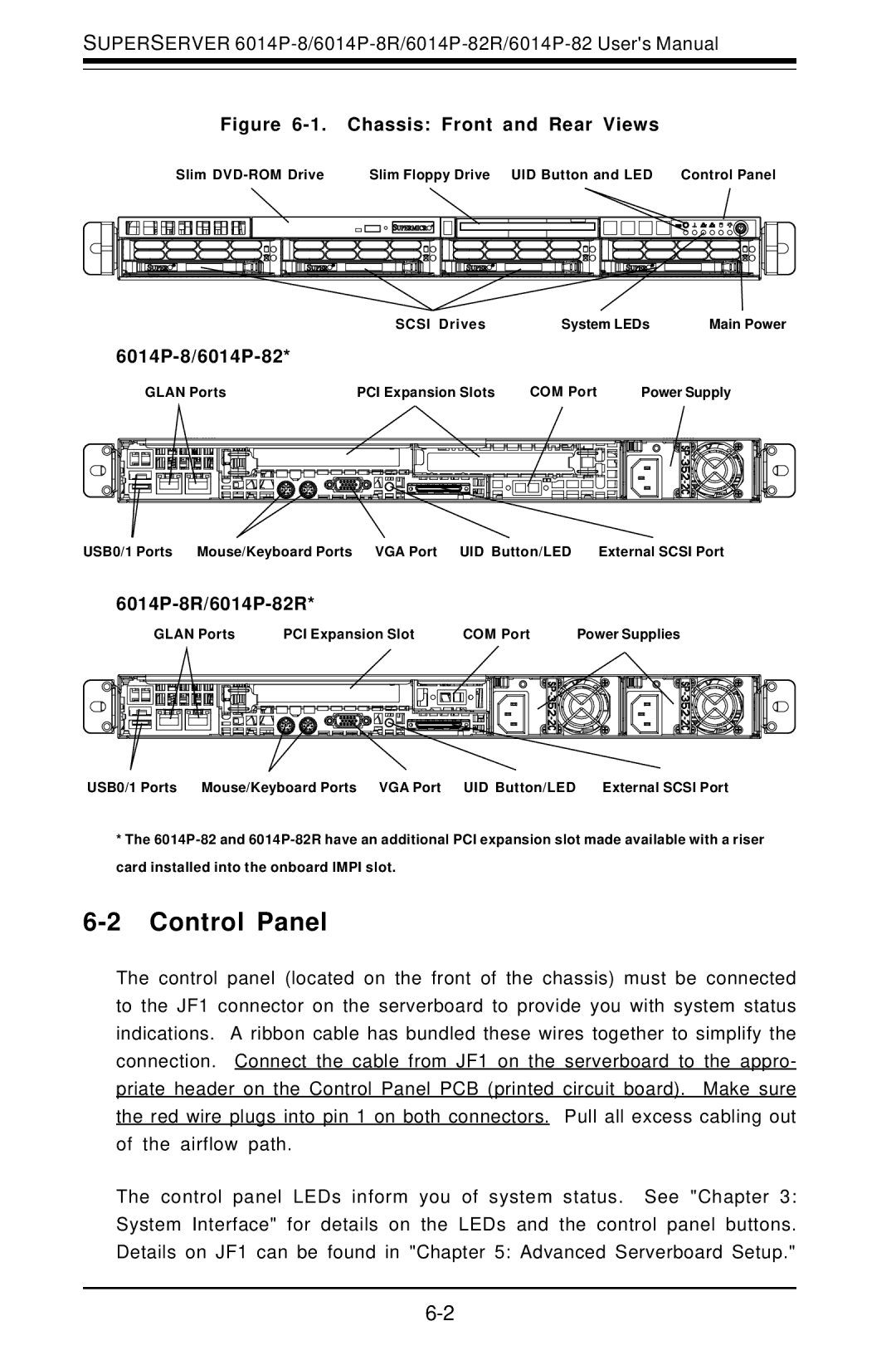
Figure 6-1. Chassis: Front and Rear Views
Slim | Slim Floppy Drive UID Button and LED Control Panel |
SCSI Drives | System LEDs | Main Power |
6014P-8/6014P-82*
|
|
| GLAN Ports |
| PCI Expansion Slots |
|
|
|
|
|
| COM Port |
|
|
|
| Power Supply | ||||||||||||||||||||||||||||||||||||||||||||||||||||||||||||||||||||||||||||
|
|
|
|
|
|
|
|
|
|
|
|
|
|
|
|
|
|
|
|
|
|
|
|
|
|
|
|
|
|
|
|
|
|
|
|
|
|
|
|
|
|
|
|
|
|
|
|
|
|
|
|
|
|
|
|
|
|
|
|
|
|
|
|
|
|
|
|
|
|
|
|
|
|
|
|
|
|
|
|
|
|
|
|
|
|
|
|
|
|
|
|
|
|
|
|
|
|
|
|
|
|
|
|
|
|
|
|
|
|
|
|
|
|
|
|
|
|
|
|
|
|
|
|
|
|
|
|
|
|
|
|
|
|
|
|
|
|
|
|
|
|
|
|
|
|
|
|
|
|
|
|
|
|
|
|
|
|
|
|
|
|
|
|
|
|
|
|
|
|
|
|
|
|
|
|
|
|
|
|
|
|
|
|
|
|
|
|
USB0/1 Ports Mouse/Keyboard Ports VGA Port UID Button/LED External SCSI Port
6014P-8R/6014P-82R*
GLAN Ports | PCI Expansion Slot | COM Port | Power Supplies |
USB0/1 Ports Mouse/Keyboard Ports VGA Port UID Button/LED | External SCSI Port |
*The
6-2 Control Panel
The control panel (located on the front of the chassis) must be connected to the JF1 connector on the serverboard to provide you with system status indications. A ribbon cable has bundled these wires together to simplify the connection. Connect the cable from JF1 on the serverboard to the appro- priate header on the Control Panel PCB (printed circuit board). Make sure the red wire plugs into pin 1 on both connectors. Pull all excess cabling out of the airflow path.
The control panel LEDs inform you of system status. See "Chapter 3: System Interface" for details on the LEDs and the control panel buttons. Details on JF1 can be found in "Chapter 5: Advanced Serverboard Setup."