SUPERSERVER
5-11 Floppy/Hard Disk and SCSI Drive Connections
Note the following when connecting the floppy and hard disk drive cables:
•The floppy disk drive cable has seven twisted wires.
•A red mark on a wire typically designates the location of pin 1.
•A single floppy disk drive ribbon cable has 34 wires and two connectors to provide for two floppy disk drives. The connector with twisted wires always connects to drive A, and the connector that does not have twisted wires always connects to drive B.
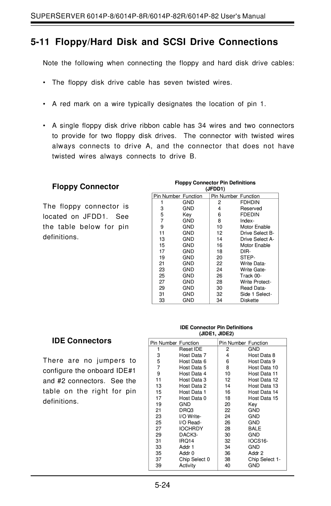
Floppy Connector
Floppy Connector Pin Definitions
(JFDD1)
|
| Pin Number Function | Pin Number Function | ||
The floppy connector is | 1 | GND | 2 | FDHDIN | |
3 | GND | 4 | Reserved | ||
located on JFDD1. | See | 5 | Key | 6 | FDEDIN |
the table below for | pin | 7 | GND | 8 | Index- |
9 | GND | 10 | Motor Enable | ||
definitions. |
| 11 | GND | 12 | Drive Select B- |
| 13 | GND | 14 | Drive Select A- | |
|
| 15 | GND | 16 | Motor Enable |
|
| 17 | GND | 18 | DIR- |
|
| 19 | GND | 20 | STEP- |
|
| 21 | GND | 22 | Write Data- |
|
| 23 | GND | 24 | Write Gate- |
|
| 25 | GND | 26 | Track 00- |
|
| 27 | GND | 28 | Write Protect- |
|
| 29 | GND | 30 | Read Data- |
|
| 31 | GND | 32 | Side 1 Select- |
|
| 33 | GND | 34 | Diskette |
IDE Connectors
There are no jumpers to configure the onboard IDE#1 and #2 connectors. See the table on the right for pin definitions.
IDE Connector Pin Definitions
(JIDE1, JIDE2)
Pin Number Function | Pin Number Function | ||
1 | Reset IDE | 2 | GND |
3 | Host Data 7 | 4 | Host Data 8 |
5 | Host Data 6 | 6 | Host Data 9 |
7 | Host Data 5 | 8 | Host Data 10 |
9 | Host Data 4 | 10 | Host Data 11 |
11 | Host Data 3 | 12 | Host Data 12 |
13 | Host Data 2 | 14 | Host Data 13 |
15 | Host Data 1 | 16 | Host Data 14 |
17 | Host Data 0 | 18 | Host Data 15 |
19 | GND | 20 | Key |
21 | DRQ3 | 22 | GND |
23 | I/O Write- | 24 | GND |
25 | I/O Read- | 26 | GND |
27 | IOCHRDY | 28 | BALE |
29 | DACK3- | 30 | GND |
31 | IRQ14 | 32 | IOCS16- |
33 | Addr 1 | 34 | GND |
35 | Addr 0 | 36 | Addr 2 |
37 | Chip Select 0 | 38 | Chip Select 1- |
39 | Activity | 40 | GND |
|
|
|
|