26 Connecting Your TV
Connecting a VCR, antenna, cable TV, or camcorder
HDMI® cables provide the best audio and picture quality.
Optical audio cable
(Sample Illustration) Optical audio cable
Optical audio cable connect receivers with Dolby® Digital or PCM
About the connection illustrations
You can connect different types and brands of devices to your TV in several different configurations. The connection illustrations in this manual are representative of typical device connections only. The input/output terminals on your devices may differ from those illustrated herein. For details on connecting and using your specific devices, refer to each device’s User’s Guide.
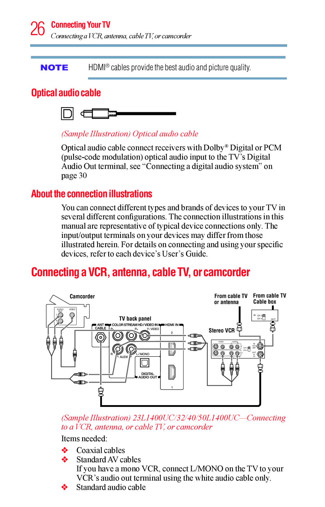
Connecting a VCR, antenna, cable TV, or camcorder
| Camcorder |
AUDIO | VIDEO |
OUT |
|
L | TV back panel |
R |
From cable TV | From cable TV | ||
or antenna | Cable box | ||
|
|
|
|
| IN CH 3 |
|
|
| CH 4 | OUT |
|
Stereo VCR ![]()
VIDEO | LAUDIOR |
| IN |
|
| IN | from |
|
| CH 3 | ANT |
|
| CH 4 |
|
|
| OUT | OUT |
|
|
| to |
| L | R | TV |
(Sample Illustration)
Items needed:
vCoaxial cables
vStandard AV cables
If you have a mono VCR, connect L/MONO on the TV to your VCR’s audio out terminal using the white audio cable only.
vStandard audio cable
