5.Installation (continued)
5.2Standard Rack Mounting
The NetDirector Console KVM Switch with IP Access is designed for mounting in a 1U rack system. For convenience, a rack mounting kit is included with your console KVM switch for quick installation. The various mounting options are explained in the sections that follow.
Standard Rack Mounting
The standard rack mounting brackets that come attached to the console KVM switch allow the unit to be installed in a standard 1U rack by a single individual.
1.Slide out the rear mounting brackets from the console and mount both brackets (separate from the console) to the inside rear of a standard 1U rack system using
2.Take the console and gently slide it into the two
2-Post Rackmounting
The console KVM switch can also be mounted in a
The mounting hardware allows for the console to be opened with the drawer in any position.
5.3 Single-Stage Installation
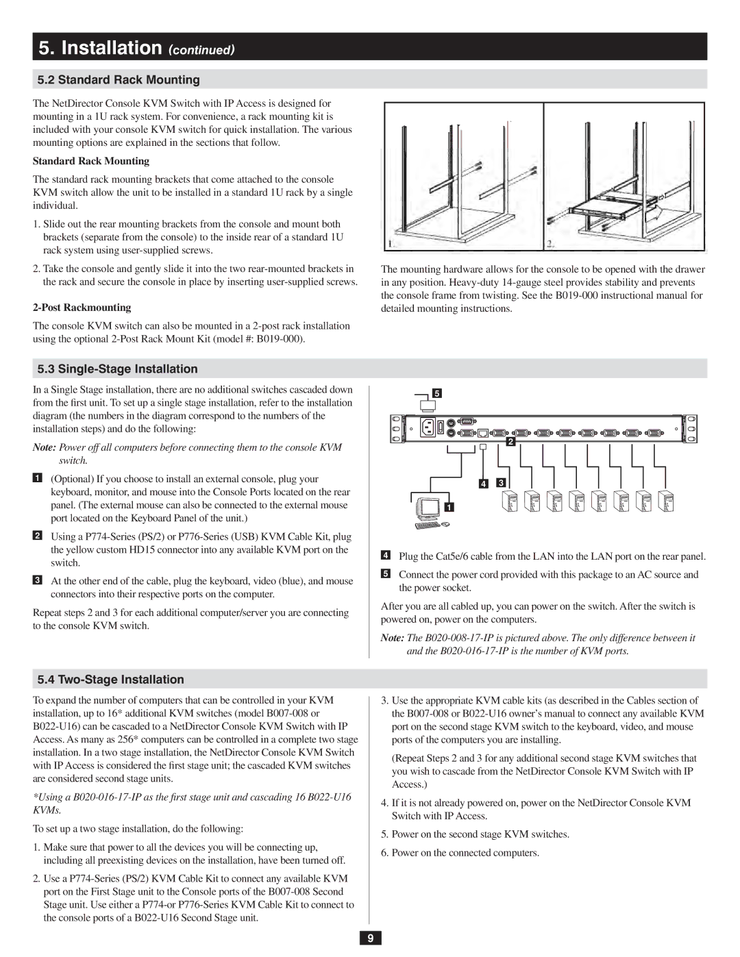
In a Single Stage installation, there are no additional switches cascaded down from the first unit. To set up a single stage installation, refer to the installation diagram (the numbers in the diagram correspond to the numbers of the installation steps) and do the following:
Note: Power off all computers before connecting them to the console KVM switch.
1(Optional) If you choose to install an external console, plug your keyboard, monitor, and mouse into the Console Ports located on the rear panel. (The external mouse can also be connected to the external mouse port located on the Keyboard Panel of the unit.)
2Using a
3At the other end of the cable, plug the keyboard, video (blue), and mouse connectors into their respective ports on the computer.
Repeat steps 2 and 3 for each additional computer/server you are connecting to the console KVM switch.
5
2
4 3
1
4Plug the Cat5e/6 cable from the LAN into the LAN port on the rear panel.
5Connect the power cord provided with this package to an AC source and the power socket.
After you are all cabled up, you can power on the switch. After the switch is powered on, power on the computers.
Note: The
5.4 Two-Stage Installation
To expand the number of computers that can be controlled in your KVM installation, up to 16* additional KVM switches (model
*Using a
To set up a two stage installation, do the following:
1.Make sure that power to all the devices you will be connecting up, including all preexisting devices on the installation, have been turned off.
2.Use a
3.Use the appropriate KVM cable kits (as described in the Cables section of the
(Repeat Steps 2 and 3 for any additional second stage KVM switches that you wish to cascade from the NetDirector Console KVM Switch with IP
Access.)
4.If it is not already powered on, power on the NetDirector Console KVM
Switch with IP Access.
5.Power on the second stage KVM switches.
6.Power on the connected computers.
9
