Th Street, Chicago, IL 60609 USA
Table of Contents
KX Models
Basic Operation
Technical Specifications
KTV Models
SU40K SU60K SU60KTV SU80KTV
SU80K Model
Model Capacity SU80K 80kVA/64kW
Control Panel Features
Features
Advanced Features
Front and Rear Panel Features
3a SU40KX front
3b SU40KX rear
3c SU40K front
3d SU40K rear
3e SU80K front
3f SU80K rear
System Layout
Internal Battery Layout
Operating Principles
Opening and Closing the Unit
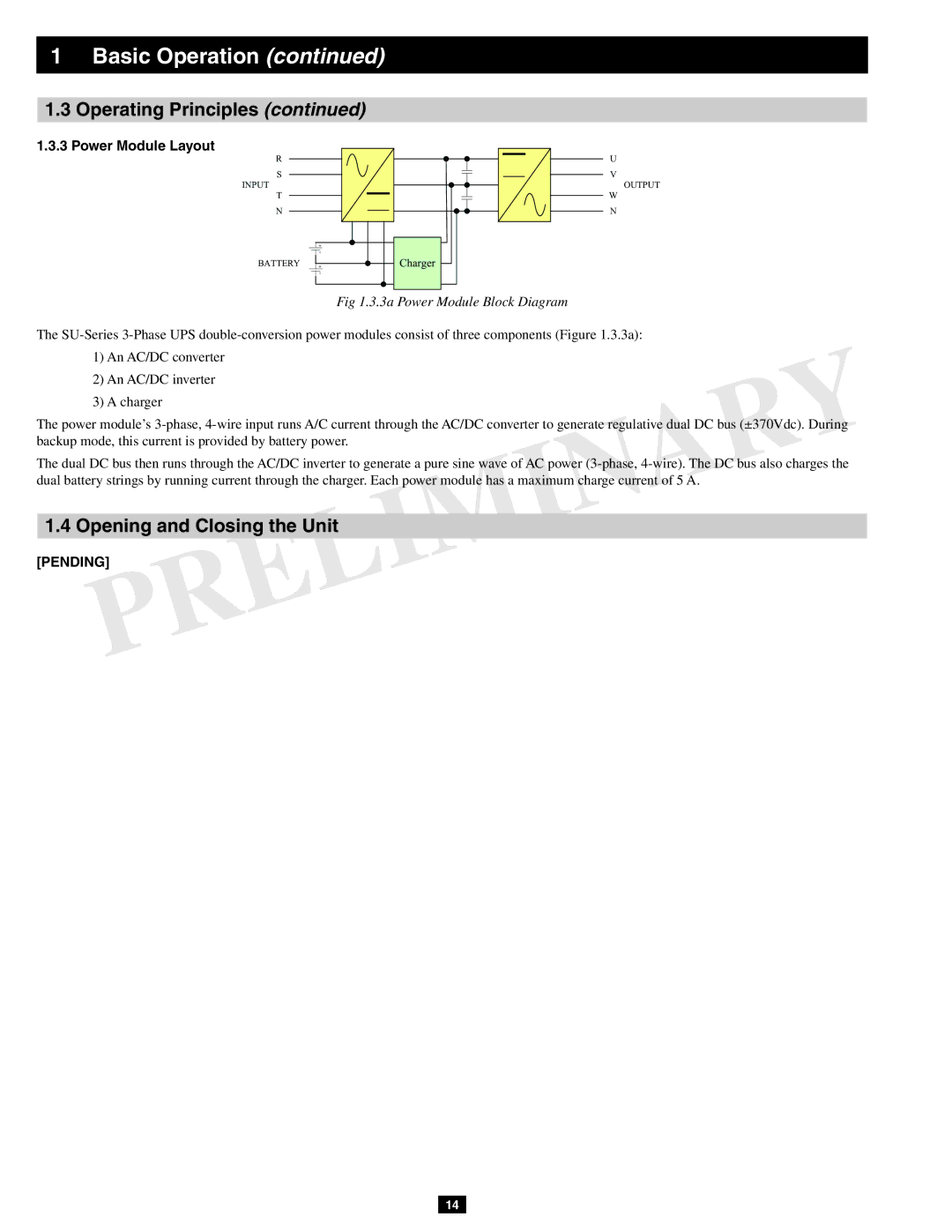
Power Module Layout
3a Power Module Block Diagram
Auto Bypass Mode Single UPS
Online Normal Mode Single UPS
Battery Backup Mode Single UPS
Manual Bypass Mode Single UPS
Auto Bypass Mode Parallel UPS
Online Mode Parallel UPS
Battery Backup Mode Parallel UPS
Manual Bypass Mode Parallel UPS
Hot Standby Mode Parallel UPS
Preliminary Checklist Single UPS
Control Panel and Breaker Diagrams
Normal LED Battery LED Bypass LED Fault LED
Standard Start-Up Procedure Single UPS
Battery Start-Up Procedure Single UPS
Manual Bypass Procedure Single UPS
Shutdown Procedure Single UPS
Preliminary Checklist Parallel UPS
Start-Up Procedure Parallel UPS
Shutdown Procedure Parallel UPS
Manual Bypass Procedure Parallel UPS
Switching from Manual Bypass to Normal Mode Parallel UPS
Printed Circuit Boards PCB
SU80KX SU60KX SU40KX SU80KTV SU20KX
PCB Location System
F3 FB M LA, LB, LC, LD
Models
LA, LB, LC
LA, LB, LC, LD F1BYP F1MAIN F2BYP F2MAIN LCD
PCB Location Power Module
PCB Board Name Description
1c SU40KX Block Diagram
Block and Wiring Diagrams
1a SU20KX Block Diagram
KX Models
Theory of Operation
DC Auxiliary Power Circuit
Auxiliary Power Failure Detection
Output Current Detection
W18
Input Voltage Detection
Located at NH-SYS-M board System MCU and Control Circuit
Output Voltage Detection
Located at NH-SYS-M board System MCU and Control Circuit
Battery Voltage Detection
UP10B
Bypass SCR Short-Circuit Detection
Scrst R
Bypass SCR Driver
TSA1
Watchdog for System MCU
LCD Panel Control Circuit
To LCD
Fan Control Circuit
Located on NH-SYS-M board System MCU and Control Circuit
Bypass SCR Temperature Detection
Communication Circuit for RS232
RS232 Port
Communication Circuit for Slots
Communication Circuit for Output Dry Contact
Output DRY Contact
Communication Circuit for Input Dry Contact and Repo
Input DRY Contact
External Battery Cabinet Temperature Detection
EXTBTEMP1
Detection Circuit for Manual Bypass Switch
Detection Circuit for Output Breaker
Control Circuit for Power Module
Centralok
To PM1 to PM2
CM93
CM106 CM109
Control Circuit for External Parallel
Theory of Operation
01 RS232 Port
Emergency Power Off EPO
Communication
02a Front Control Panel
02c
Remote Emergency Power Off Repo
02b
Setting Eeprom on the NH-M Board
Polling and Updating Eeprom
Calibrating Eeprom Gain
Setting Output Dry Contact Status
Upgrading Firmware for the System Board
Output Manual Bypass Main Input
N C S T G R G I N
G R a D E
Communication
Upgrading Firmware for the Power Module
PM1
U P S T G R G I N
Link the UPS to a PC via the RS232 port
Communication
Communication
Communication
T I N G L O W E D
Downloading the Event Log
Front View of SU20KX and SU40KX
Internal Battery
Battery Strings
Installing and Removing Internal Batteries
Terminals
Damage the UPS system and create a serious risk of personal
Battery compartment. Warning Observe proper polarity by
Connecting negative to negative black to black and positive
Injury and property damage
Battery Cabinet
2a BP480V26B 2b BP480V40C
Internal Battery
2d W1 and W2 Cables
2e Connection between UPS and Battery Cabinet
2f Wiring between UPS and Battery Cabinet
1a Warning Message List
Troubleshooting
Alarm Messages
1b Power Module Warning Message List
Condition
Troubleshooting Flow Charts
Main VOLT/FREQ NOK
Main Sequence NOK
Bypass VOLT/FREQ NOK
Bypass Static Switch Over Temperature
Bypass Sequence NOK
Bypass Static Switch Fault
Bypass Static Switch Overload
Same fault message? Replace the power module
UPS Internal Comm Abnormal
10a
Battery Test Fail
Battery Over Charge
Battery BAD
11a 11b
Bypass FAN Failure
12a 12b 12c
Transformer Overheat
13a 13b
PS Output Volt NOK
14a 14b
PS EXT Parallel Comm Abnormal
15a 15b
Parallel Failure
16a 16b
Redundancy Loss
17a
Power Module
Failure Power Module Identify
115
116
Power Module Replacement
AC Input DC Input Output
119
120
UPS Procedure
Preventive Maintenance
Safety Overview
Suggested tools and supplies
Internal Battery Procedure
Software Tools
Appendix a Service Equipment and Tools
Recommended Equipment and Tools
Multi-Meter Oscilloscope
Table B.1
Appendix B Torque Table
KX Models
Fig B.a
Table B.3
Models
Table B.2
Fig B.b Fig B.c
Fig B.d
KTV Models
Table B.4
NH-SYS-R Board
Appendix C PCB and Test Point
NH-SYS-P Board