3 Communication
Warning: Do not use the paralleling cable that came with the UPS system for these procedures. Use a RS232 cable.
3.01 RS232 Port
The UPS provides a RS232 port in one
3.1) Sets EEPROM on the
3.2) Sets Output Dry Contact status
3.3) Upgrades the system board’s firmware
3.4) Upgrades the power module’s DSP firmware
3.5) Downloads the event log of the UPS
Use the straight through serial connection to communicate with the RS232 port. The pin assignment of the RS232 port
Figure 3.01a RS232 Pin Assignment
Pin 2: PC receives line
Pin 3: PC transmits line
Pin 5: Signal ground.
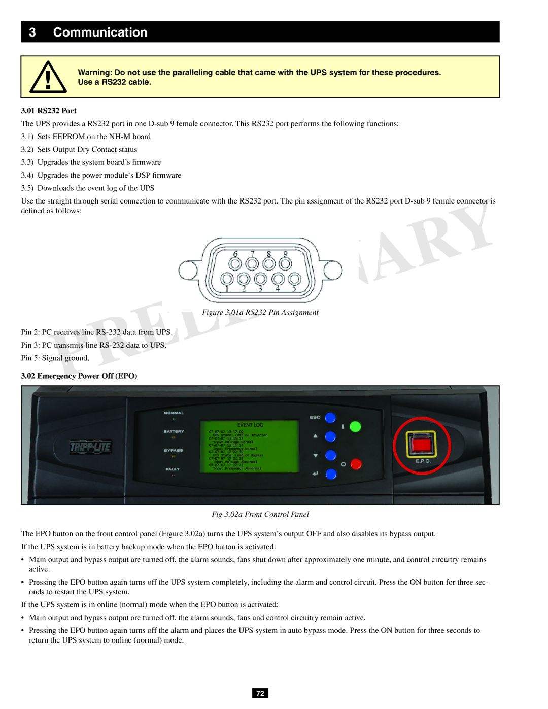
3.02 Emergency Power Off (EPO)
Fig 3.02a Front Control Panel
The EPO button on the front control panel (Figure 3.02a) turns the UPS system’s output OFF and also disables its bypass output. If the UPS system is in battery backup mode when the EPO button is activated:
•Main output and bypass output are turned off, the alarm sounds, fans shut down after approximately one minute, and control circuitry remains active.
•Pressing the EPO button again turns off the UPS system completely, including the alarm and control circuit. Press the ON button for three sec- onds to restart the UPS system.
If the UPS system is in online (normal) mode when the EPO button is activated:
•Main output and bypass output are turned off, the alarm sounds, fans and control circuitry remain active.
•Pressing the EPO button again turns off the alarm and places the UPS system in auto bypass mode. Press the ON button for three seconds to return the UPS system to online (normal) mode.
72