5 Troubleshooting (continued)
5.2 Troubleshooting Flow Charts
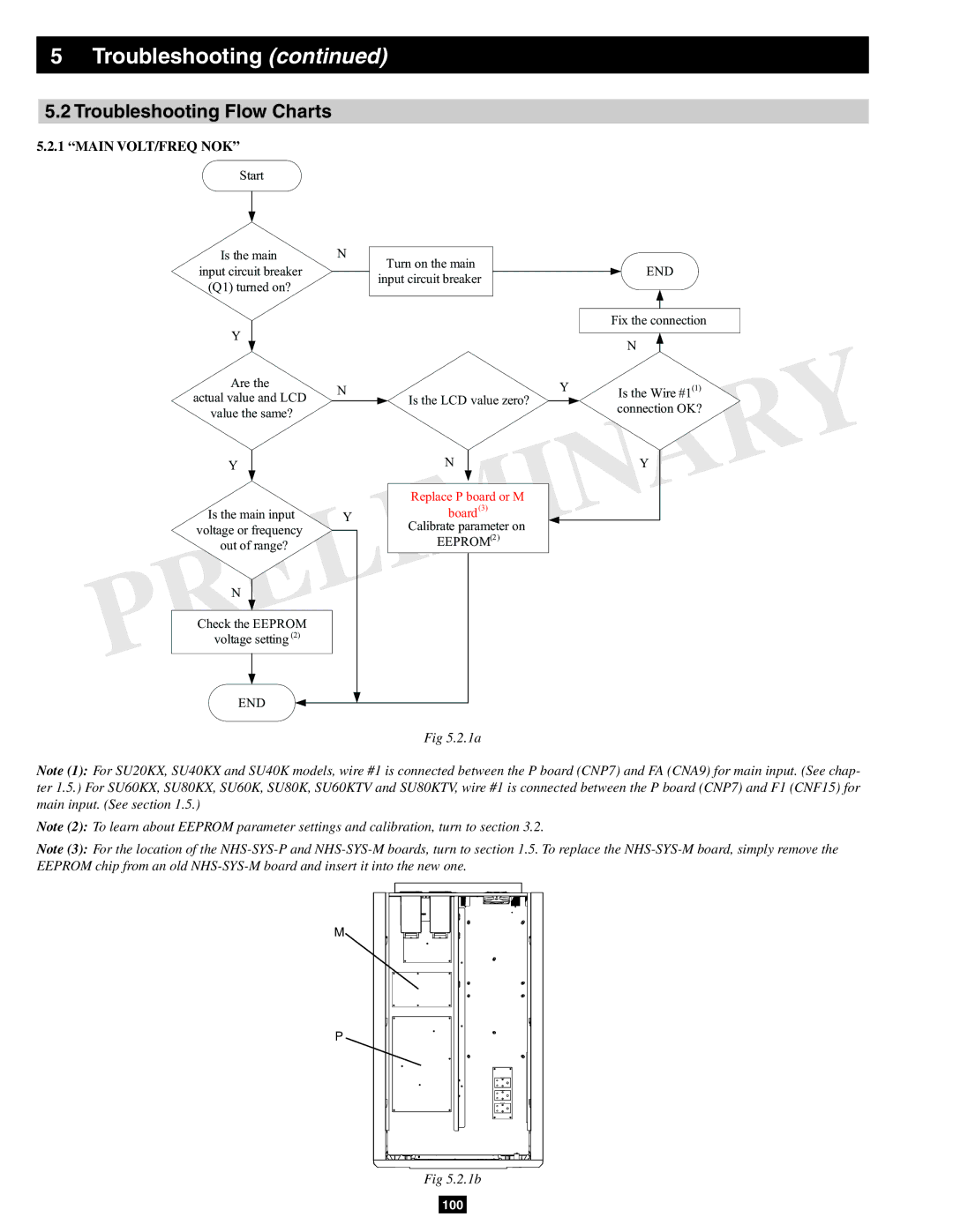
5.2.1“MAIN VOLT/FREQ NOK”
Start
Is the main input circuit breaker
(Q1) turned on?
Y
Are the
actual value and LCD value the same?
Y
Is the main input voltage or frequency out of range?
N
Check the EEPROM voltage setting (2)
END
N
Turn on the main input circuit breaker
NY Is the LCD value zero?
N
Replace P board or M
Yboard(3) Calibrate parameter on
EEPROM(2)
Fig 5.2.1a
END
Fix the connection
N
Is the Wire #1(1) connection OK?
Y
Note (1): For SU20KX, SU40KX and SU40K models, wire #1 is connected between the P board (CNP7) and FA (CNA9) for main input. (See chap- ter 1.5.) For SU60KX, SU80KX, SU60K, SU80K, SU60KTV and SU80KTV, wire #1 is connected between the P board (CNP7) and F1 (CNF15) for main input. (See section 1.5.)
Note (2): To learn about EEPROM parameter settings and calibration, turn to section 3.2.
Note (3): For the location of the
M
P
Fig 5.2.1b
100
