5 Troubleshooting (continued)
5.2Troubleshooting Flow Charts (continued)
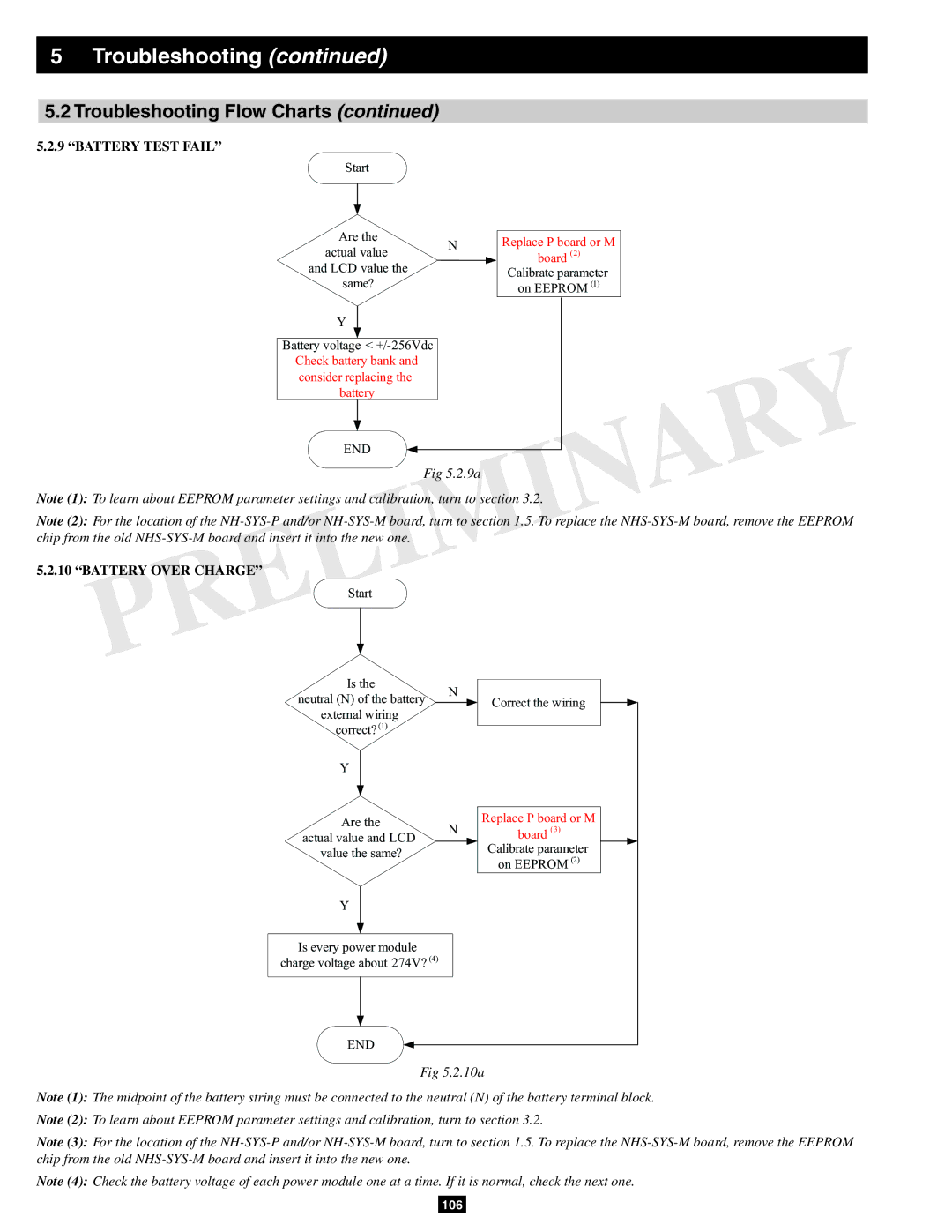
5.2.9“BATTERY TEST FAIL”
Start
Are the
N
actual value and LCD value the
same?
Y
Battery voltage <
END
Replace P board or M
board (2) Calibrate parameter on EEPROM (1)
Fig 5.2.9a
Note (1): To learn about EEPROM parameter settings and calibration, turn to section 3.2.
Note (2): For the location of the
5.2.10 “BATTERY OVER CHARGE”
Start |
|
|
| |
Is the | N |
|
| |
neutral (N) of the battery | Correct the wiring | |||
| ||||
external wiring |
|
|
| |
correct? (1) |
|
|
| |
Y |
|
|
| |
Are the | N | Replace P board or M | ||
actual value and LCD | board | (3) | ||
|
| |||
value the same? |
| Calibrate parameter | ||
| on EEPROM (2) | |||
|
| |||
Y |
|
|
| |
Is every power module |
|
|
| |
charge voltage about 274V? (4) |
|
|
| |
END |
|
|
| |
Fig 5.2.10a
Note (1): The midpoint of the battery string must be connected to the neutral (N) of the battery terminal block.
Note (2): To learn about EEPROM parameter settings and calibration, turn to section 3.2.
Note (3): For the location of the
Note (4): Check the battery voltage of each power module one at a time. If it is normal, check the next one.
106
