2 Theory of Operation (continued)
2.12 Fan Control Circuit
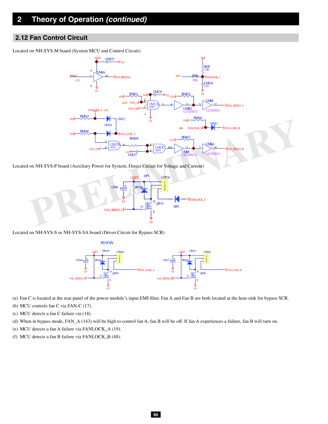
Located on NH-SYS-M board (System MCU and Control Circuit)
|
| +12VS | CM123 | G1 |
|
|
|
| 5VS |
| |
|
|
|
|
|
|
|
|
|
|
| |
|
|
|
|
|
|
|
|
|
| RM7 |
|
| 9 | UM8A |
|
|
|
|
|
| 10K |
| |
|
|
|
| (18) | RM6 |
|
|
| |||
1 |
| 16 |
|
|
| FANLOCK_C |
| ||||
(17) |
|
|
|
|
|
| 10K |
|
| ||
|
|
|
|
|
|
|
| CM136 |
| ||
|
|
|
|
|
|
|
|
|
|
| |
| 8 |
|
|
|
|
|
|
|
| 104 |
|
|
| G1 |
| RM161 | 5VS | CM124 | G1 | RM162 | G1 |
| |
|
|
|
|
|
| ||||||
|
|
|
| 5VS | 14 |
| +12VS |
|
| UM8E |
|
|
|
|
|
|
|
|
|
|
| ||
|
|
|
| (143) FAN_A | 1 | UM12A 3 |
|
|
|
| |
|
|
|
| + | 4 | 13 | 5 | 12 | FAN_SPEED_A | ||
| FANLOCK_A (19) | FAN_ON | 2- | 4081 |
| UM8D |
| ULN2003A | |||
|
|
|
|
| ULN2003A |
|
| ||||
|
|
|
|
| 7 |
|
|
|
|
| |
| RM163 |
|
|
|
|
| RM164 |
|
| ||
5VS |
|
| DM32 |
|
|
|
|
| |||
|
|
|
| G1 |
| 5VS |
| DM33 |
| ||
|
|
|
|
|
|
|
|
| |||
|
|
| DM34 |
|
|
|
|
|
|
| |
|
|
|
|
|
| (48) FANLOCK_B |
| FAN_LOCK_B | |||
| RM166 |
|
|
|
|
|
| ||||
5VS |
|
| FAN_LOCK_A |
|
|
|
|
|
|
| |
|
|
|
|
|
| RM167 |
|
|
| ||
|
|
|
| RM168 |
|
| +12VS |
|
|
| |
|
|
| 5 |
|
|
|
|
|
| ||
|
|
|
|
|
|
|
| UM8G |
| ||
|
|
| UM12B 4 |
| 8 | 106 | 11 | 7 |
| ||
| FAN ON | 6 4081 |
| UM12C | 10 | FAN SPEED B | |||||
|
| G1 |
| 9 4081 |
| UM8F |
| ULN2003A | |||
|
|
|
| CM127 |
|
|
| ULN2003A |
|
| |
|
|
|
|
|
|
|
|
|
| ||
Located on
| +12VS | DP5 | CNP16 |
|
| ||
|
|
| 1 |
CP96 | RP194 |
| 2 |
| 3 | ||
|
|
| |
G1 |
| D | FANLOCK C |
G | QP14 | ||
FAN SPEED C |
| DP6 | |
| S |
| |
|
|
|
G1
Located on
|
| TOFAN | ||
| +12VS |
| DSA10 | CNSA4 |
|
|
| ||
|
|
|
| 1 |
CSA16 | RSA21 |
| 2 | |
| 3 | |||
|
|
|
| |
G1 |
| G |
| D QSA9 |
FAN_SPEED_A |
|
|
| |
|
|
| S | |
|
|
|
| |
|
| +12VS | DSA11 | CNSA5 |
|
|
| ||
|
|
|
| 1 |
| CSA17 | RSA22 |
| 2 |
|
| 3 | ||
|
|
|
| |
FAN_LOCK_A | G1 |
| D | FAN_LOCK_B |
| G | QSA8 | ||
| FAN_SPEED_B |
|
| |
|
| S |
| |
|
|
|
|
G1 | G1 |
(a)Fan C is located at the rear panel of the power module’s input EMI filter. Fan A and Fan B are both located at the
(b)MCU controls fan C via
(c)MCU detects a fan C failure via (18).
(d)When in bypass mode, FAN_A (143) will be high to control fan A; fan B will be off. If fan A experiences a failure, fan B will turn on.
(e)MCU detects a fan A failure via FANLOCK_A (19).
(f)MCU detects a fan B failure via FANLOCK_B (48).
60