6 Power Module (continued)
6.1Failure Power Module Identify (continued)
5)(Use this step to shut down the UPS with load protection)
Set UPS to manual bypass mode.
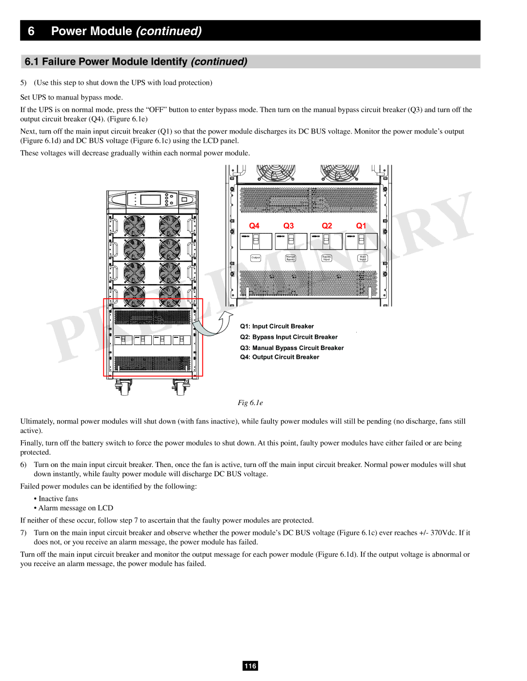
If the UPS is on normal mode, press the “OFF” button to enter bypass mode. Then turn on the manual bypass circuit breaker (Q3) and turn off the output circuit breaker (Q4). (Figure 6.1e)
Next, turn off the main input circuit breaker (Q1) so that the power module discharges its DC BUS voltage. Monitor the power module’s output (Figure 6.1d) and DC BUS voltage (Figure 6.1c) using the LCD panel.
These voltages will decrease gradually within each normal power module.
Q4 | Q3 | Q2 | Q1 | |
Output | Manual | Bypass | Main | |
Bypass | Input | Input | ||
|
Q1: Input Circuit Breaker
Q2: Bypass Input Circuit Breaker
Q3: Manual Bypass Circuit Breaker
Q4: Output Circuit Breaker
Fig 6.1e
Ultimately, normal power modules will shut down (with fans inactive), while faulty power modules will still be pending (no discharge, fans still active).
Finally, turn off the battery switch to force the power modules to shut down. At this point, faulty power modules have either failed or are being protected.
6)Turn on the main input circuit breaker. Then, once the fan is active, turn off the main input circuit breaker. Normal power modules will shut down instantly, while faulty power module will discharge DC BUS voltage.
Failed power modules can be identified by the following:
•Inactive fans
•Alarm message on LCD
If neither of these occur, follow step 7 to ascertain that the faulty power modules are protected.
7)Turn on the main input circuit breaker and observe whether the power module’s DC BUS voltage (Figure 6.1c) ever reaches +/- 370Vdc. If it does not, or you receive an alarm message, the power module has failed.
Turn off the main input circuit breaker and monitor the output message for each power module (Figure 6.1d). If the output voltage is abnormal or you receive an alarm message, the power module has failed.
