2 Theory of Operation (continued)
2.9Bypass SCR Driver (continued)
(a)The bypass SCR driver signal “BYPSTS1” is controlled by MCU or “TOBYP_J” according to the signal “CENTRAL_OK.”
(b)“CENTRAL_OK” is the output of MCU watchdog. If MCU is operating normally, “CENTRAL_OK” will be high and the bypass SCR driver signal will be controlled by “BYPSTS” (1) (high active). If MCU is not operating normally, “CENTRAL_OK” will be low and the bypass SCR driver signal will be controlled by “TOBYP_J” (high active).
(c)UM9 is a 45 kHz
(d)The “TOBYP_J” signal is limited by “#TOBYP_I.”
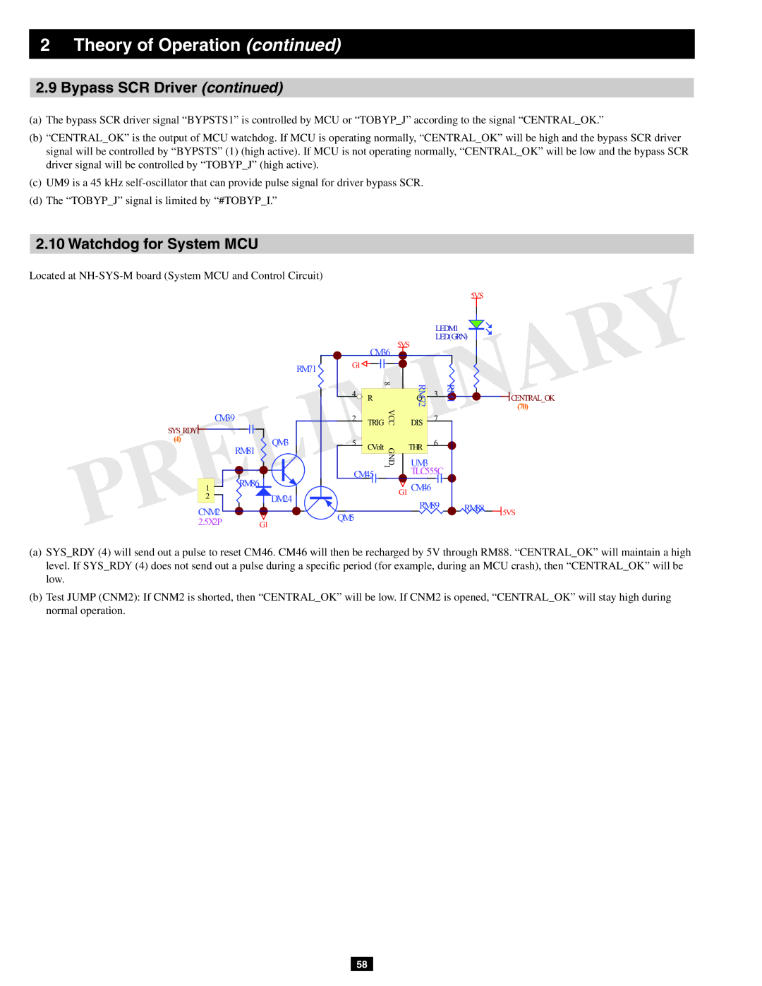
2.10Watchdog for System MCU
Located at
RM71
CM39
SYS RDY![]()
(4)![]() QM3
QM3
RM81
1 | RM86 |
2 | DM24 |
CNM2
2.5X2P G1
|
|
|
|
| 5VS |
|
|
| LEDM1 |
| |
|
| 5VS | LED(GRN) |
| |
| CM36 |
|
|
| |
|
|
|
|
| |
G1 |
| RM72 |
|
|
|
4 | 8 | 3 | RM1 |
| |
| R | Q |
|
| CENTRAL OK |
|
|
|
|
| (70) |
2 TRIG | VCC | DIS 7 |
|
| ||
5 | CVolt | GND | THR | 6 |
|
|
|
|
|
| |||
|
| UM3 |
|
|
| |
|
| 1 |
|
|
| |
CM45 |
| TLC555C |
|
| ||
|
|
|
|
| ||
|
|
| G1 CM46 |
|
|
|
QM5 |
|
| RM89 | RM88 | 5VS | |
|
|
|
|
| ||
|
|
|
|
|
| |
(a)SYS_RDY (4) will send out a pulse to reset CM46. CM46 will then be recharged by 5V through RM88. “CENTRAL_OK” will maintain a high level. If SYS_RDY (4) does not send out a pulse during a specific period (for example, during an MCU crash), then “CENTRAL_OK” will be low.
(b)Test JUMP (CNM2): If CNM2 is shorted, then “CENTRAL_OK” will be low. If CNM2 is opened, “CENTRAL_OK” will stay high during normal operation.
58