1 Basic Operation (continued)
1.2Features
1.2.1Advanced Features:
•True
•Low input current THD allows 1:1 generator sizing for maximum efficiency and cost savings
•Internal N+1 power module redundancy (except for SU20KX model)
•
•Up to 80kVA capacity in a compact footprint; up to 160kVA in parallel redundancy (1+1) configuration
•High input power factor and high efficiency with low thermal loss and low noise
•Simplified,
•Redundant auxiliary power and control circuits
•Dual input design with separated rectifier and bypass input (SU20K, SU40K, SU60K, SU80K only)
•All models support external battery cabinets for extended battery backup runtime
•
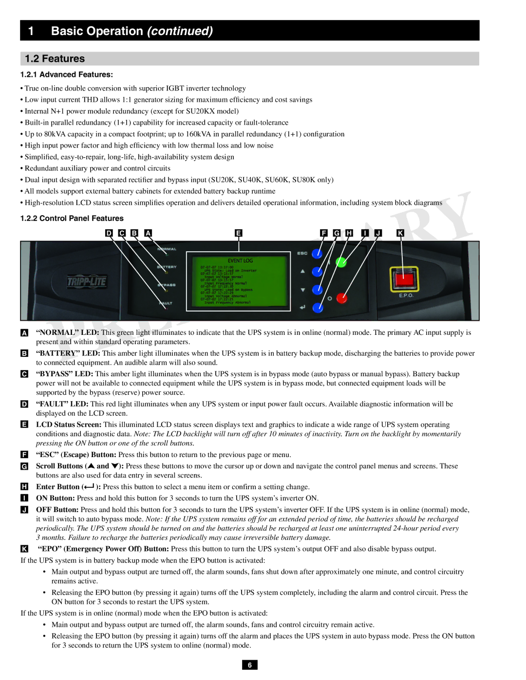
1.2.2 Control Panel Features
•“NORMAL” LED: This green light illuminates to indicate that the UPS system is in online (normal) mode. The primary AC input supply is present and within standard operating parameters.
•“BATTERY” LED: This amber light illuminates when the UPS system is in battery backup mode, discharging the batteries to provide power to connected equipment. An audible alarm will also sound.
•“BYPASS” LED: This amber light illuminates when the UPS system is in bypass mode (auto bypass or manual bypass). Battery backup power will not be available to connected equipment while the UPS system is in bypass mode, but connected equipment loads will be supported by the bypass (reserve) power source.
•“FAULT” LED: This red light illuminates when any UPS system or input power fault occurs. Available diagnostic information will be displayed on the LCD screen.
•LCD Status Screen: This illuminated LCD status screen displays text and graphics to indicate a wide range of UPS system operating
conditions and diagnostic data. Note: The LCD backlight will turn off after 10 minutes of inactivity. Turn on the backlight by momentarily pressing the ON button or one of the scroll buttons.
•“ESC” (Escape) Button: Press this button to return to the previous page or menu.
•Scroll Buttons (![]() and
and ![]() ): Press these buttons to move the cursor up or down and navigate the control panel menus and screens. These buttons are also used for data entry in several screens.
): Press these buttons to move the cursor up or down and navigate the control panel menus and screens. These buttons are also used for data entry in several screens.
•Enter Button (![]() ): Press this button to select a menu item or confirm a setting change.
): Press this button to select a menu item or confirm a setting change.
•ON Button: Press and hold this button for 3 seconds to turn the UPS system’s inverter ON.
•OFF Button: Press and hold this button for 3 seconds to turn the UPS system’s inverter OFF. If the UPS system is in online (normal) mode,
it will switch to auto bypass mode. Note: If the UPS system remains off for an extended period of time, the batteries should be recharged periodically. The UPS system should be turned on and the batteries should be recharged at least one uninterrupted
•“EPO” (Emergency Power Off) Button: Press this button to turn the UPS system’s output OFF and also disable bypass output.
If the UPS system is in battery backup mode when the EPO button is activated:
•Main output and bypass output are turned off, the alarm sounds, fans shut down after approximately one minute, and control circuitry remains active.
•Releasing the EPO button (by pressing it again) turns off the UPS system completely, including the alarm and control circuit. Press the ON button for 3 seconds to restart the UPS system.
If the UPS system is in online (normal) mode when the EPO button is activated:
•Main output and bypass output are turned off, the alarm sounds, fans and control circuitry remain active.
•Releasing the EPO button (by pressing it again) turns off the alarm and places the UPS system in auto bypass mode. Press the ON button for 3 seconds to return the UPS system to online (normal) mode.
6
