3 | End Brackets |
|
| Winding | Right End | |
Splines | Bracket | ||
Shaft | Disconnect Cable | ||
| |||
|
| Guide Hole |
Tools Needed:
Power Drill
7/16” Socket
Driver
1/2” Wrench
Step Ladder
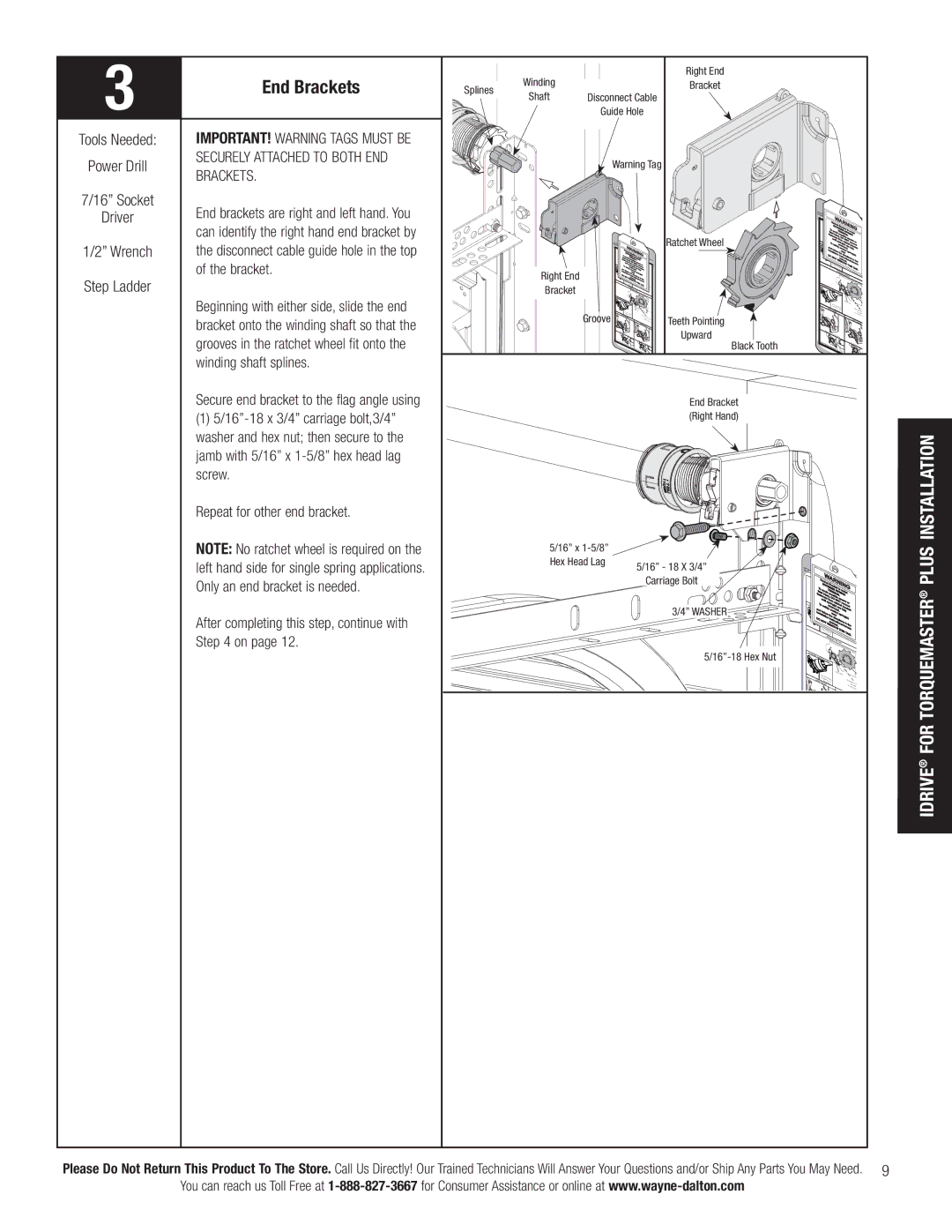
IMPORTANT! WARNING TAGS MUST BE SECURELY ATTACHED TO BOTH END BRACKETS.
End brackets are right and left hand. You can identify the right hand end bracket by the disconnect cable guide hole in the top of the bracket.
Beginning with either side, slide the end bracket onto the winding shaft so that the grooves in the ratchet wheel fit onto the winding shaft splines.
Secure end bracket to the flag angle using
(1)
Repeat for other end bracket.
Warning Tag |
label. |
|
|
|
|
| Ratchet Wheel |
Use |
|
|
|
|
|
|
this these |
| WA |
|
|
|
|
| R |
| NIN |
| ||
|
| EXTRBrack |
| |||
|
| achet | R |
|
|
|
| ffaTasottaelanivnojiudrTyp,EEoMNssSEiIbOSeltPNi.RsIuNnGdeGr | side of | ||||
Right End | iDannOsTtdoaNfullosnOalaetltiTiofrloeswslRnfypwtrEirmhonuinMDnermsnwaetgOwOnrdo(aruiiusuVardnNc)atenEtdelcOi.cadoht.rssiTneeopetsrrnvfi/ebuesnolmrrlgwiaeyn(ocnsovtk)ehreerets |
| ||||
Bracket |
|
|
| THIS | TAG. |
|
|
|
|
|
| ||
|
|
|
|
|
| |
Groove |
|
|
|
|
| Teeth Pointing |
|
|
|
|
|
| Upward |
Black Tooth
End Bracket
(Right Hand)
Use |
|
|
|
|
|
|
|
|
|
|
|
|
this these |
|
|
|
|
|
|
|
|
|
|
|
|
label. |
|
|
| W |
|
|
|
|
|
|
| |
|
|
|
|
|
| NI |
|
|
| |||
|
|
| EX | Br |
|
|
|
| ||||
|
|
| Rachet AR |
| N | G |
|
| ||||
|
| To a | TRE acket | is |
|
| ||||||
|
| T | ME |
|
|
|
| |||||
| fatalvoid | ENSISPRIunder |
| t | ||||||||
| fastenienjruryp,oDssibOleN. | NG |
|
|
| |||||||
|
|
| untilssfromOrNOsTevere |
|
|
| ||||||
ENG |
| To sa | pwrinng(sa)tchetrebmoovre |
|
| |||||||
| iDannstdaflloalltifooewlnytihnuernwewdoaiiurdnendad.rseprfiunlrlgay(csk)et |
| ||||||||||
|
| O N | OT |
| stru |
| ctio | nsi |
|
|
| |
|
|
|
|
| ma | ctio |
|
| a | |||
|
|
| No | space | REMnual. ns/own the |
| ||||||
|
|
|
|
| OVE | THI | ners |
| ||||
|
|
| Ratchet |
|
|
|
|
|
| |||
|
|
|
| CablePawl and |
|
| S T |
|
| |||
|
|
|
|
| Drum |
|
|
| AG. |
| ||
|
|
|
|
| DISENGAGED | SIDE VIEW |
|
|
| a | ||
|
|
|
|
|
|
|
|
|
|
| ||
DI |
|
|
|
|
|
|
|
|
|
|
|
|
SENGAGED U | NDERNEATH VIEW |
|
|
|
|
|
|
| ||||
|
|
|
|
|
|
|
|
| ||||
|
|
| No space |
|
| Ratchet Pawl |
|
|
| |||
|
|
| between |
|
|
|
|
|
| |||
| UPPER | Ratchet |
|
|
| Space |
|
| ||||
|
| CablePawl and |
|
|
| betweenR | ||||||
|
|
| POSITION | Drum |
|
|
|
| ||||
|
|
|
|
|
|
|
| non- and | Cable | |||
|
|
|
|
|
|
|
|
|
|
| indicates e | |
|
|
|
|
|
|
|
|
| LOWER | POSITION | ||
|
|
|
|
|
|
|
|
|
|
| ||
| Ratchet Pawl |
|
|
|
|
|
|
|
|
| ||
|
|
| in Upper | Position |
|
|
|
|
|
| ||
|
|
|
|
|
|
|
|
|
|
| ||
UPPER | POSITION |
|
|
|
|
|
|
| Ratchet | Pawlin |
| |
| SIDE VIEW |
|
|
|
|
| Lower P | |||||
|
|
|
|
|
|
|
|
| ||||
|
|
|
|
|
|
| L |
|
|
|
|
|
INSTALLATION
NOTE: No ratchet wheel is required on the left hand side for single spring applications. Only an end bracket is needed.
After completing this step, continue with Step 4 on page 12.
5/16” x ![]()
Hex Head Lag 5/16” - 18 X 3/4” Carriage Bolt ![]()
![]()
3/4” WASHER
5/16”-18 Hex Nut
Use this
these |
|
|
|
|
|
|
|
|
|
|
|
|
|
|
|
|
label. |
|
| W |
|
|
|
|
|
|
|
|
|
|
|
| |
|
|
|
|
|
|
|
|
|
|
|
|
|
|
| ||
|
| Rachet AR | NI |
|
|
|
|
|
| |||||||
|
| EX | Br |
|
|
|
|
|
|
|
| |||||
| To |
|
| TRE acket | is | N | G |
|
|
| ||||||
|
|
|
| ME |
| u |
|
|
|
| ||||||
fat avoi TEN |
| SP |
|
|
|
|
|
| t | |||||||
f |
| alinjd po |
| SIO |
| RINnder |
|
|
|
| ||||||
asten |
| ury, | ssibl N. |
| G |
|
|
|
|
| ||||||
|
|
| ers | D |
| e s |
|
|
|
|
|
|
| |||
|
| untilsfromOrNOTevere | or |
|
|
| ||||||||||
| To s |
| prin |
| atc |
|
| re |
|
|
| |||||
|
| w |
| g(s) | het | mov | e |
|
|
| ||||||
iand f | afel nw |
| ar |
| bra |
|
|
|
| |||||||
| y unwoiund.e fullycket |
|
| |||||||||||||
nst | ollo |
| r |
| nd |
| spring( |
|
|
|
| |||||
D |
| allatiow theead |
|
|
|
|
| |||||||||
O N |
| nin |
| dire | ctio |
| s) |
|
|
| ||||||
|
|
| OT | ma |
| ctio |
| nsi |
|
|
|
| a | |||
|
|
|
| RE |
| nual |
| ns/ | n th | e |
|
| ||||
|
| No |
|
| MO . |
|
| own |
|
|
| |||||
|
| Ratchet |
|
|
| VE |
| THI |
|
| ers |
|
| |||
|
|
| CablePawl and |
|
|
|
|
|
| S T |
|
|
|
| ||
|
|
|
| Drum |
|
|
|
|
|
|
| AG. |
| e | ||
|
|
|
| DISENGAGED SIDE |
|
|
|
|
|
|
|
| a | |||
|
|
|
| VIEW |
|
|
|
|
|
| ||||||
DISENGAGED U |
|
|
|
|
|
|
|
|
|
|
|
|
|
|
|
|
NDER | NEATH |
|
|
|
|
|
|
|
|
|
|
|
|
| ||
|
|
|
| VIEW |
|
|
|
|
|
|
|
|
|
|
|
|
|
|
|
|
|
|
| Ratchet | Pawl |
|
|
|
|
|
| ||
|
| No | space |
|
|
|
|
|
|
|
|
|
|
| ||
UPPER | Ratchet | between |
|
|
|
|
|
| Space |
|
|
| ||||
| CablePawl and |
|
|
|
|
|
|
| between |
| ||||||
|
| POSITION Drum |
|
|
|
|
|
|
|
|
| R | ||||
|
|
|
|
|
|
|
|
|
|
|
| non- |
| Cable | ||
|
|
|
|
|
|
|
|
|
|
|
|
|
| indicates en | ||
®PLUS FORTORQUEMASTER
®IDRIVE
Please Do Not Return This Product To The Store. Call Us Directly! Our Trained Technicians Will Answer Your Questions and/or Ship Any Parts You May Need. 9 You can reach us Toll Free at