pr | 10 | Cable Adjustments |
| ||
|
| |
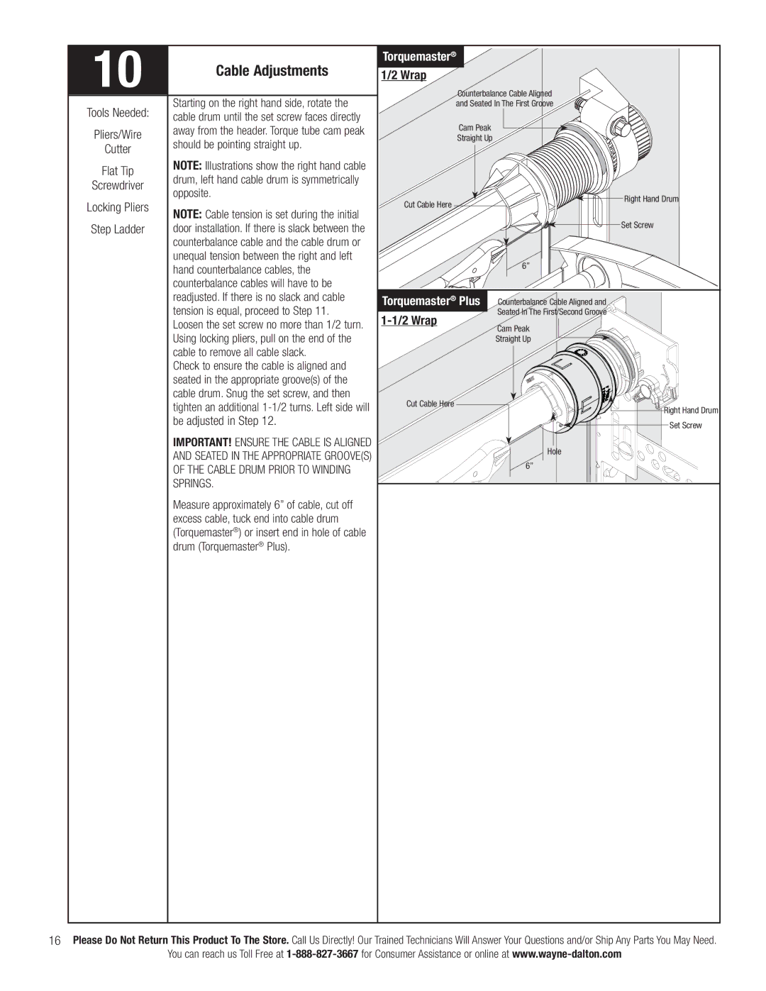
| Tools Needed: | Starting on the right hand side, rotate the |
| cable drum until the set screw faces directly | |
|
| |
| Pliers/Wire | away from the header. Torque tube cam peak |
| should be pointing straight up. | |
| Cutter | |
|
| |
| Flat Tip | NOTE: Illustrations show the right hand cable |
| drum, left hand cable drum is symmetrically | |
| Screwdriver | |
| opposite. | |
|
| |
| Locking Pliers | NOTE: Cable tension is set during the initial |
|
| |
| Step Ladder | door installation. If there is slack between the |
|
| counterbalance cable and the cable drum or |
|
| unequal tension between the right and left |
|
| hand counterbalance cables, the |
|
| counterbalance cables will have to be |
Torquemaster®
1/2 Wrap
Counterbalance Cable Aligned
and Seated In The First Groove
Cam Peak
Straight Up
![]()
![]()
![]()
![]()
![]() Right Hand Drum Cut Cable Here
Right Hand Drum Cut Cable Here ![]()
![]()
Set Screw
6”
readjusted. If there is no slack and cable |
tension is equal, proceed to Step 11. |
Loosen the set screw no more than 1/2 turn. |
Using locking pliers, pull on the end of the |
cable to remove all cable slack. |
Check to ensure the cable is aligned and |
seated in the appropriate groove(s) of the |
cable drum. Snug the set screw, and then |
tighten an additional |
be adjusted in Step 12. |
IMPORTANT! ENSURE THE CABLE IS ALIGNED |
AND SEATED IN THE APPROPRIATE GROOVE(S) |
OF THE CABLE DRUM PRIOR TO WINDING |
SPRINGS. |
Measure approximately 6” of cable, cut off |
excess cable, tuck end into cable drum |
(Torquemaster®) or insert end in hole of cable |
drum (Torquemaster® Plus). |
Torquemaster® Plus
1-1/2 Wrap
Cut Cable Here
Counterbalance Cable Aligned and
Seated In The First/Second Groove
Cam Peak
Straight Up
Hole
6”
Right Hand Drum Set Screw
16Please Do Not Return This Product To The Store. Call Us Directly! Our Trained Technicians Will Answer Your Questions and/or Ship Any Parts You May Need.
You can reach us Toll Free at
