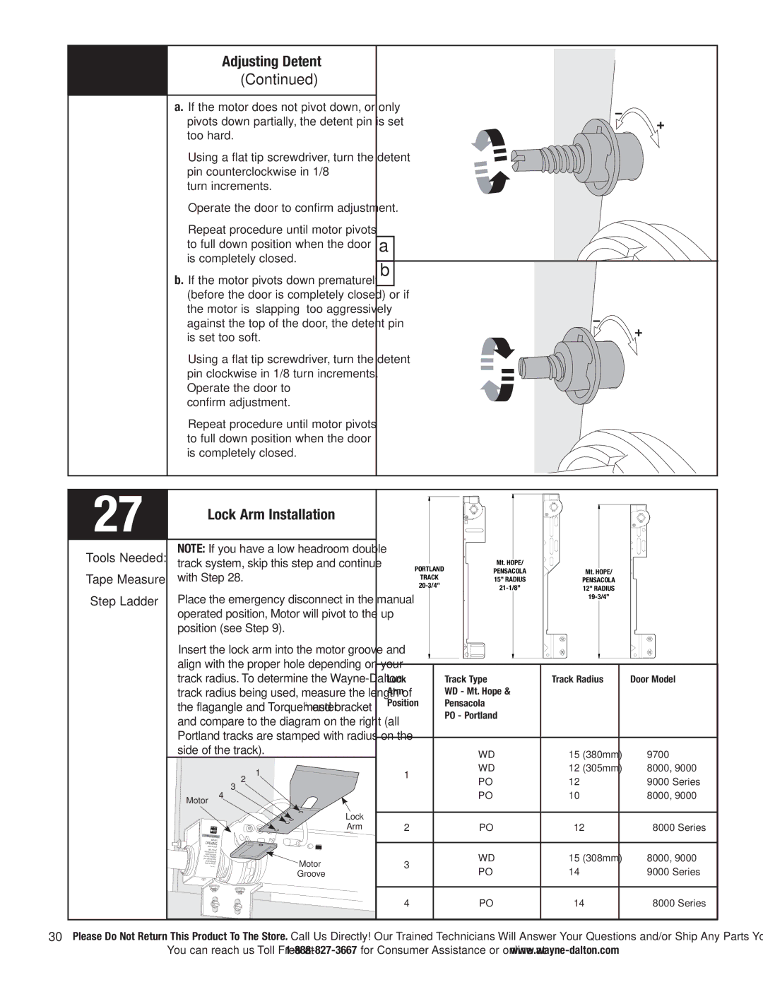
Adjusting Detent
(Continued)
a. If the motor does not pivot down, or only pivots down partially, the detent pin is set too hard.
Using a flat tip screwdriver, turn the detent pin counterclockwise in 1/8
turn increments.
Operate the door to confirm adjustment.
Repeat procedure until motor pivots to full down position when the door is completely closed.
b. If the motor pivots down prematurely (before the door is completely closed) or if the motor is “slapping” too aggressively against the top of the door, the detent pin is set too soft.
Using a flat tip screwdriver, turn the detent pin clockwise in 1/8 turn increments. Operate the door to
confirm adjustment.
Repeat procedure until motor pivots to full down position when the door is completely closed.
a |
b |
27 | Lock Arm Installation |
|
Tools Needed:
Tape Measure
Step Ladder
NOTE: If you have a low headroom double track system, skip this step and continue with Step 28.
Place the emergency disconnect in the manual operated position, Motor will pivot to the up position (see Step 9).
Insert the lock arm into the motor groove and align with the proper hole depending on your track radius. To determine the
|
|
|
|
|
|
| Mt. HOPE/ |
|
|
|
|
| |
|
|
|
|
|
|
|
|
|
|
|
| ||
|
|
|
|
|
|
|
|
|
|
|
| ||
|
|
|
|
|
|
|
|
|
|
|
| ||
PORTLAND |
|
|
|
|
|
|
|
| |||||
|
|
| PENSACOLA |
|
|
| Mt. HOPE/ | ||||||
TRACK |
|
|
|
|
|
| |||||||
|
|
| 15” RADIUS |
|
|
| PENSACOLA | ||||||
20- | 3/4” |
|
|
|
|
|
| ||||||
|
|
|
|
|
| 12” RADIUS | |||||||
|
|
|
|
|
|
|
|
|
|
|
| ||
|
|
|
|
|
|
|
|
|
|
|
|
|
|
|
|
|
|
|
|
|
|
|
|
|
|
|
|
|
|
|
|
|
|
|
|
|
|
|
|
|
|
Lock | Track Type | Track Radius | Door Model |
Arm | WD - Mt. Hope & |
|
|
Position | Pensacola |
|
|
| PO - Portland |
|
|
|
|
|
|
| WD | 15”(380mm) | 9700 |
| WD | 12”(305mm) | 8000, 9000 |
Motor
1
2
3
4
1 | 12” | 9000 Series |
PO | ||
PO | 10” | 8000, 9000 |
Lock
Arm
2 | PO | 12” | 8000 Series |
what’s OPENING your world?
With
Motor
Groove
3 | WD | 15”(308mm) | 8000, 9000 | |
PO | 14” | 9000 Series | ||
| ||||
|
|
|
| |
4 | PO | 14” | 8000 Series |
30Please Do Not Return This Product To The Store. Call Us Directly! Our Trained Technicians Will Answer Your Questions and/or Ship Any Parts You May Need.
You can reach us Toll Free at
