20 | Sensor Wire Installation | |
(Required on all 8000 Series and | ||
other Non Pinch Resistant Doors) | ||
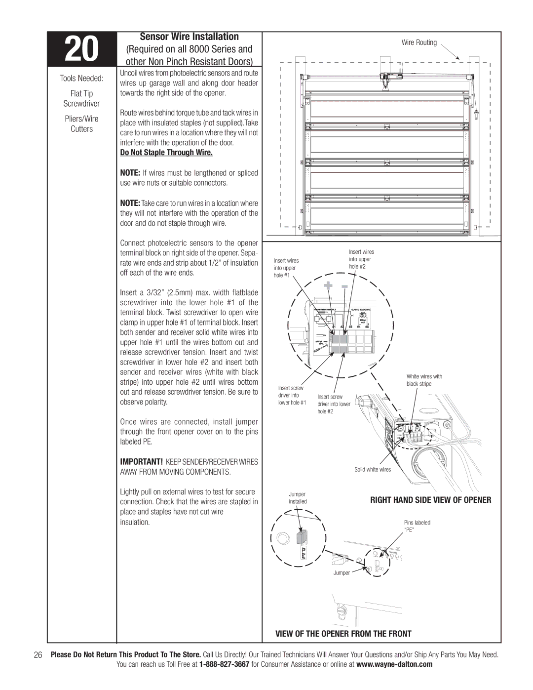
Tools Needed: | Uncoil wires from photoelectric sensors and route | |
wires up garage wall and along door header | ||
| ||
Flat Tip | towards the right side of the opener. | |
Screwdriver | Route wires behind torque tube and tack wires in | |
Pliers/Wire | ||
place with insulated staples (not supplied).Take | ||
Cutters | ||
care to run wires in a location where they will not | ||
| ||
| interfere with the operation of the door. | |
| Do Not Staple Through Wire. | |
| NOTE: If wires must be lengthened or spliced | |
| use wire nuts or suitable connectors. | |
| NOTE: Take care to run wires in a location where | |
| they will not interfere with the operation of the | |
| door and do not staple through wire. | |
| Connect photoelectric sensors to the opener | |
| terminal block on right side of the opener. Sepa- | |
| rate wire ends and strip about 1/2” of insulation | |
| off each of the wire ends. | |
| Insert a 3/32” (2.5mm) max. width fl atblade | |
| screwdriver into the lower hole #1 of the | |
| terminal block. Twist screwdriver to open wire | |
| clamp in upper hole #1 of terminal block. Insert | |
| both sender and receiver solid white wires into | |
| upper hole #1 until the wires bottom out and | |
| release screwdriver tension. Insert and twist | |
| screwdriver in lower hole #2 and insert both | |
| sender and receiver wires (white with black | |
| stripe) into upper hole #2 until wires bottom | |
| out and release screwdriver tension. Be sure to | |
| observe polarity. | |
| Once wires are connected, install jumper | |
| through the front opener cover on to the pins | |
| labeled PE. | |
| IMPORTANT! KEEP SENDER/RECEIVER WIRES | |
| AWAY FROM MOVING COMPONENTS. | |
| Lightly pull on external wires to test for secure | |
| connection. Check that the wires are stapled in | |
| place and staples have not cut wire | |
| insulation. | |
|
|
|
|
|
|
|
|
|
| Wire Routing |
| Insert wires |
|
|
|
|
|
| |
Insert wires | into upper |
|
|
|
|
|
| |
into upper | hole #2 |
|
|
|
|
|
| |
hole #1 |
|
|
|
|
|
|
|
|
|
|
|
|
|
|
|
| White wires with |
Insert screw |
|
|
|
|
|
|
| black stripe |
|
|
|
|
|
|
|
| |
driver into | Insert screw |
|
|
|
|
|
|
|
lower hole #1 | driver into lower |
|
|
|
|
|
|
|
| hole #2 |
|
|
|
|
|
|
|
|
| Solid white wires |
|
|
| |||
Jumper |
| RIGHT HAND SIDE VIEW OF OPENER | ||||||
installed |
| |||||||
|
|
|
|
|
|
|
| Pins labeled |
|
|
|
|
|
|
|
| “PE” |
|
|
|
|
| Controls |
| ||
|
| Learn |
| S1 | S2 | S3 |
|
|
|
|
|
|
|
| S4 | D | |
|
|
|
|
|
|
|
| |
|
| P | 1 | 2 |
|
|
|
|
| Jumper | E |
|
|
|
|
|
|
|
|
|
|
|
|
|
| |
VIEW OF THE OPENER FROM THE FRONT | ||||||||
26Please Do Not Return This Product To The Store. Call Us Directly! Our Trained Technicians Will Answer Your Questions and/or Ship Any Parts You May Need.
You can reach us Toll Free at