|
|
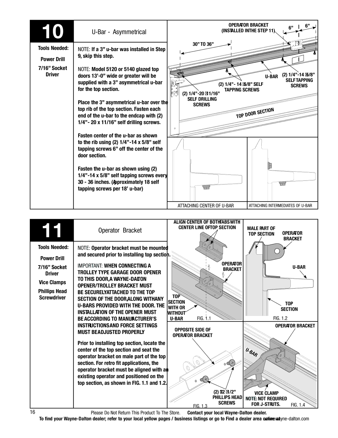
10 |
|
| |
|
|
Tools Needed: | NOTE: If a 3” |
Power Drill | 9, skip this step. |
| |
7/16” Socket | NOTE: Model 5120 or 5140 glazed top |
Driver | doors |
| supplied with a 3” asymmetrical |
| for the top section. |
| Place the 3” asymmetrical |
| top rib of the top section. Fasten each |
| end of the |
| 1/4”- 20 x 11/16” self drilling screws. |
| Fasten center of the |
| to the rib using (2) |
| tapping screws 6” off the center of the |
| door section. |
| Fasten the |
| |
| 30 - 36 inches. (Approximately 18 self |
| tapping screws per 18’ |
|
|
operator bracket |
| 6” | 6” |
(installed in the step | 11) |
| |
|
|
30” to 36”
|
| (2) | ||
|
| SELF tapping | ||
(2) 1/4”- 14 x 5/8” Self | ||||
SCREWS | ||||
(2) | ||||
| ||||
SELF DRILLING |
|
|
| |
SCREWS |
|
|
| |
top | door | section |
| |
|
| |||
|
|
| ||
|
|
|
|
|
|
|
|
|
|
|
|
|
|
|
|
|
|
|
|
|
|
|
|
|
|
|
|
|
|
|
|
|
|
|
|
|
|
|
|
|
|
|
|
|
|
|
|
|
|
|
|
|
|
|
|
|
|
|
|
|
|
|
|
|
|
|
|
|
|
|
|
|
|
|
|
|
|
|
|
|
|
|
|
|
|
|
|
|
|
|
|
|
|
|
|
|
|
|
|
|
|
|
|
|
|
|
|
|
|
|
|
|
|
|
|
|
|
|
|
|
|
|
|
|
|
|
|
|
|
|
|
|
|
|
|
|
|
|
|
|
|
|
|
|
|
|
|
|
|
|
|
|
|
|
|
|
|
|
|
|
|
|
|
|
|
|
|
|
|
|
|
|
|
|
|
|
|
|
|
|
|
|
|
|
|
|
|
|
|
|
|
|
|
|
|
|
|
|
|
|
|
|
|
|
|
|
|
|
|
|
|
|
|
|
|
|
|
|
|
|
|
|
|
|
|
|
|
|
|
|
|
|
|
|
|
|
|
|
|
|
|
|
|
|
|
|
|
|
|
|
|
|
|
|
|
|
|
|
|
|
|
|
|
|
|
|
|
|
|
|
|
|
|
|
|
| ||||||||
|
| attaching center of | attaching intermediates of | |||||||||||||||
|
|
|
|
|
|
|
|
|
|
|
|
|
|
|
|
|
|
|
11 |
| Align center of both tabs with |
|
|
|
|
| ||
Operator Bracket | center line of top section | Male part of | Operator | ||||||
|
|
|
| top section | |||||
|
|
|
|
| |||||
|
|
|
|
|
|
|
| Bracket | |
Tools Needed: | NOTE: Operator bracket must be mounted |
|
|
|
|
|
|
|
|
Power Drill | and secured prior to installing top section. |
|
|
|
|
|
|
|
|
|
|
| Operator |
|
|
|
|
| |
7/16” Socket | IMPORTANT: WHEN CONNECTING A |
|
|
|
|
|
| ||
|
| Bracket |
|
|
|
| |||
Driver | TROLLEY TYPE GARAGE DOOR OPENER |
|
|
|
|
|
|
| |
|
|
|
|
|
|
|
| ||
Vice Clamps | TO THIS DOOR, A |
|
|
|
|
|
|
|
|
OPENER/TROLLEY BRACKET MUST |
|
|
|
|
|
|
|
| |
Phillips Head |
|
|
|
|
|
|
|
| |
BE SECURELY ATTACHED TO THE TOP | Top |
|
|
|
|
|
|
| |
Screwdriver | SECTION OF THE DOOR, ALONG WITH ANY |
|
|
|
|
|
|
| |
| section |
|
|
|
|
|
| Top | |
| With or |
|
|
|
|
|
| ||
|
|
|
|
|
|
| section | ||
| INSTALLATION OF THE OPENER MUST |
|
|
|
|
|
| ||
| without |
|
|
|
|
|
| ||
| FIG. 1.1 |
|
|
|
| FIG. 1.2 | |||
| BE ACCORDING TO MANUFACTURER’S |
|
|
|
| ||||
| INSTRUCTIONS AND FORCE SETTINGS | Opposite side of |
|
|
|
| Operator Bracket | ||
| MUST BE ADJUSTED PROPERLY. |
|
|
|
|
|
| ||
| Operator bracket |
|
|
|
|
|
| ||
|
|
|
|
|
|
|
| ||
| Prior to installing top section, locate the |
|
|
|
|
|
| r |
|
|
|
|
|
|
|
|
|
| |
|
|
|
|
|
|
| a |
| |
|
|
|
|
|
| b |
|
| |
| center of the top section and seat the |
|
|
| - |
|
|
| |
|
|
|
| U |
|
|
|
| |
| operator bracket on male part of the top |
|
|
|
|
|
|
|
|
| section. For retro fit applications, the |
|
|
|
|
|
|
|
|
| operator bracket must be aligned with an |
|
|
|
|
|
|
|
|
| existing operator and positioned on the |
|
|
|
|
|
|
|
|
| top section, as shown in FIG. 1.1 and 1.2. |
|
|
|
|
|
|
|
|
|
|
|
| (2) #12 x 1/2” |
|
|
| Vice clamp |
|
|
|
|
| Phillips head | NOTE: not required | ||||
|
|
| FIG. 1.3 | screws |
|
| for | FIG. 1.4 | |
16 |
|
|
|
|
| ||||
Please Do Not Return This Product To The Store. Contact your local |
| ||||||||
To find your