21 |
| Winding | |
|
| ||
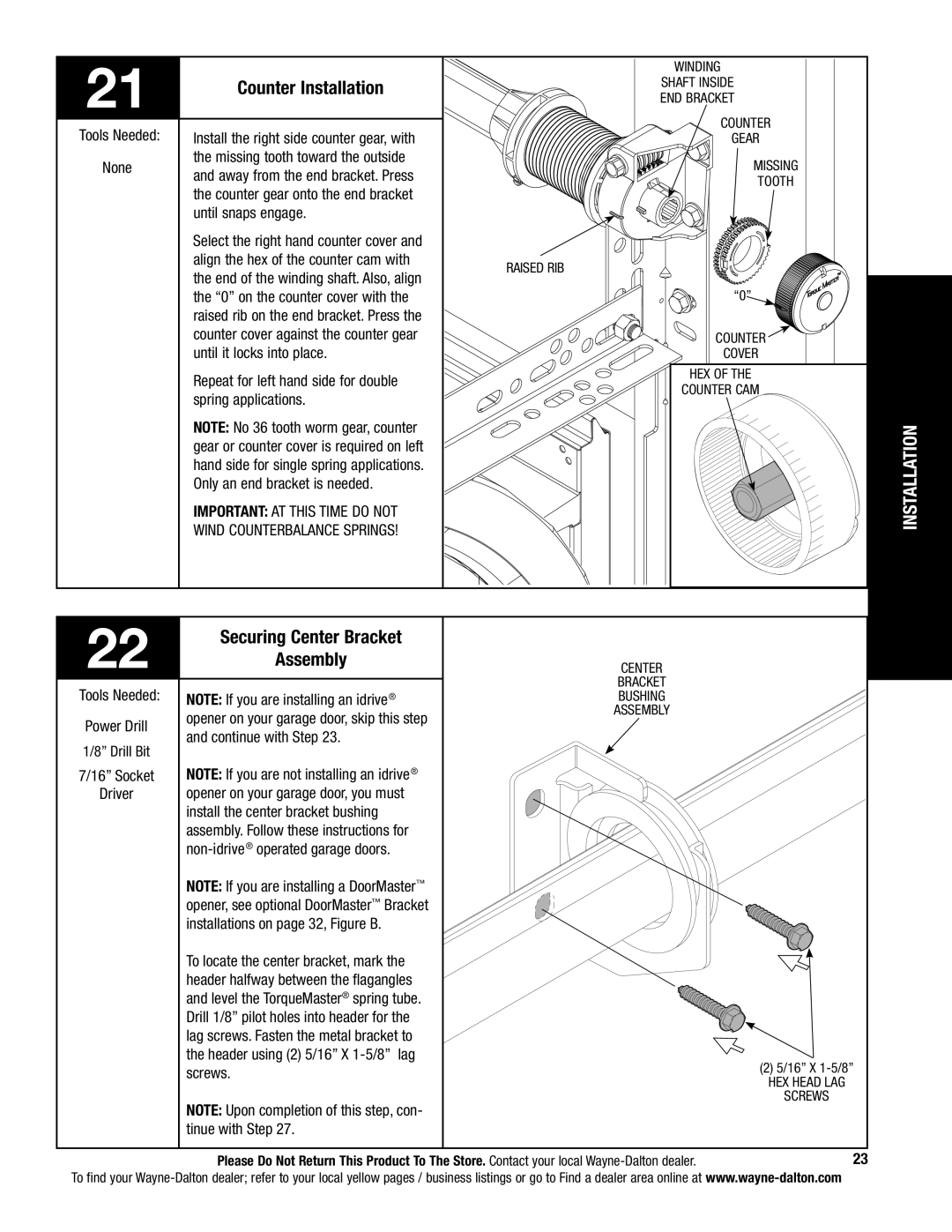
| Counter Installation | Shaft Inside | |
| End Bracket | ||
|
| ||
Tools Needed: | Install the right side counter gear, with | Counter | |
Gear | |||
None | the missing tooth toward the outside | Missing | |
and away from the end bracket. Press | |||
| Tooth | ||
| the counter gear onto the end bracket | ||
|
| ||
| until snaps engage. |
| |
| Select the right hand counter cover and |
| |
| align the hex of the counter cam with | Raised Rib | |
| the end of the winding shaft. Also, align | ||
|
| ||
| the “0” on the counter cover with the | “0” | |
| raised rib on the end bracket. Press the |
| |
| counter cover against the counter gear | Counter | |
| until it locks into place. | Cover | |
| Repeat for left hand side for double | Hex of the | |
| Counter Cam | ||
| spring applications. | ||
|
| ||
| NOTE: No 36 tooth worm gear, counter | INSTALLATION | |
| gear or counter cover is required on left | ||
|
| ||
| hand side for single spring applications. |
| |
| Only an end bracket is needed. |
| |
| IMPORTANT: At this time do not |
| |
| wind Counterbalance Springs! |
|
22 | Securing Center Bracket |
|
Assembly | CENTER | |
|
| BRACKET |
Tools Needed: |
| |
NOTE: If you are installing an idrive® | bushing | |
Power Drill | opener on your garage door, skip this step | ASSEMBLY |
| ||
and continue with Step 23. |
| |
1/8” Drill Bit |
| |
|
| |
7/16” Socket | NOTE: If you are not installing an idrive® |
|
Driver | opener on your garage door, you must |
|
| install the center bracket bushing |
|
| assembly. Follow these instructions for |
|
|
|
NOTE: If you are installing a DoorMaster™ opener, see optional DoorMaster™ Bracket installations on page 32, Figure B.
To locate the center bracket, mark the |
| |
header halfway between the flagangles |
| |
and level the TorqueMaster® spring tube. |
| |
Drill 1/8” pilot holes into header for the |
| |
lag screws. Fasten the metal bracket to |
| |
the header using (2) 5/16” x | (2) 5/16” x | |
screws. | ||
hex head lag | ||
| ||
NOTE: Upon completion of this step, con- | screws | |
| ||
tinue with Step 27. |
| |
Please Do Not Return This Product To The Store. Contact your local | 23 |
To find your