� | Trolley Installation for | Determine the | Level |
| ||||
Standard Lift | track radius being used: |
| HIGH ARC |
| ||||
|
|
|
|
| ||||
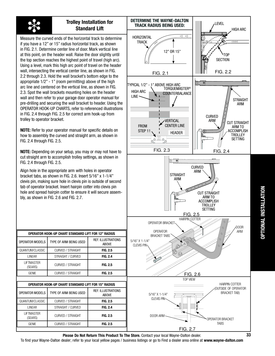
Measure the curved ends of the horizontal track to determine | Horizontal |
|
|
| ||||
if you have a 12” or 15” radius horizontal track, as shown | track |
|
|
|
|
| ||
|
|
|
|
|
| |||
in FIG. 2.1. Determine center line of door. Mark vertical line |
|
| 12” or 15” |
|
|
| ||
at this point, on the header wall. Raise the door slightly until |
|
|
| TOP |
| |||
|
|
|
|
| ||||
the top section reaches the highest point of travel (high arc). |
|
|
| SECTION |
| |||
Using a level, mark this high arc point of travel on the header |
|
|
|
|
|
| ||
wall, intersecting the vertical center line, as shown in FIG. |
|
| FIG. 2.1 | FIG. 2.2 |
| |||
2.2 through 2.3. Hold the wall bracket’s bottom edge to the |
|
|
|
|
| |||
|
|
|
|
|
| |||
appropriate 1/2” - 1” (room permitting) above of the high | Typical 1/2” - 1” above high arc |
|
|
| ||||
arc line and centered on the vertical line, as shown in FIG. |
|
|
| |||||
HIGH ARC |
| Torquemaster® |
|
|
| |||
2.3. Spot the wall brackets mounting holes on the header |
| Counterbalance |
|
|
| |||
wall and then refer to your garage door operator manual for | line |
|
|
| Straight |
| ||
|
|
|
|
| ||||
|
|
|
| arm |
| |||
operator |
|
|
|
|
|
| ||
in FIG. 2.4 through FIG. 2.5 for correct arm |
|
|
| Curved |
|
| ||
trolley to operator bracket. |
|
|
|
|
|
| ||
|
|
| Vertical | arm | Cut Straight |
| ||
|
|
| From |
| center line |
|
| |
NOTE: Refer to your operator manual for specific details on |
|
| arm to |
| ||||
step 11 | Header |
| accomplish |
| ||||
how to assembly the curved and straight arm, as shown in |
|
|
| trolley |
| |||
|
|
|
|
| ||||
FIG. 2.4 through FIG. 2.5. |
|
|
|
|
| setting |
| |
|
|
|
|
|
|
| ||
NOTE: Depending on your setup, you may or may not have to |
|
| FIG. 2.3 | FIG. 2.4 |
| |||
cut straight arm to accomplish trolley settings, as shown in |
|
|
|
|
|
| ||
FIG. 2.4 through FIG. 2.5. |
|
|
| CURVED |
|
| ||
Align hole in the appropriate arm with holes in operator |
|
|
|
| ||||
|
| arm |
|
|
| |||
bracket tabs, as shown in FIG. 2.6. Insert 5/16” x |
|
| Straight |
|
|
| ||
clevis pin, making sure hole in clevis pin is outside of second |
|
| arm |
|
|
| ||
|
|
|
|
|
| |||
tab of operator bracket. Insert hairpin cotter into clevis pin |
|
| FIG. 2.5 |
|
| INSTALLATION | ||
hole and spread hairpin cotter to ensure it will secure assem- |
|
|
|
| ||||
|
| Cut Straight |
|
| ||||
bly, as shown in FIG. 2.6 and FIG. 2.7. |
|
|
|
| arm to |
|
| |
|
|
|
|
| accomplish |
|
| |
|
|
|
|
|
| trolley |
|
|
|
|
|
|
|
| setting |
|
|
|
|
|
|
| Hairpin Cotter |
|
| OPTIONAL |
|
|
|
| Operator Bracket |
|
| ||
|
|
|
|
|
|
| ||
|
|
|
|
|
|
| Door |
|
Operator |
|
| Operator |
| Arm |
| ||
|
| Bracket tabs |
|
|
| |||
|
|
|
|
|
|
|
| |
Operator models | Type of arm Being used | Ref. Illustrations | 5/16” x |
|
|
|
| |
above |
|
|
|
| ||||
Clevis pin |
|
|
|
|
| |||
|
|
|
|
|
|
| ||
|
|
|
|
|
|
|
| |
Quantum/classic | Curved / Straight | Fig. 2.5 |
|
|
|
|
|
|
Linear | Straight / Curved | Fig. 2.4 |
|
|
|
|
|
|
Liftmaster | Curved / Straight | Fig. 2.5 |
|
|
|
|
|
|
(sears) |
|
|
|
|
|
| ||
|
|
|
|
|
|
|
| |
Genie | Curved / Straight | Fig. 2.5 |
|
| FIG. 2.6 |
|
|
|
|
|
|
|
| Top view |
|
|
|
Operator |
|
|
|
| Hairpin Cotter |
| ||
|
| Ref. Illustrations |
|
|
| (Outside of operator |
| |
Operator models | Type of arm Being used |
| 5/16” x |
| bracket tab) |
| ||
above |
|
|
| |||||
|
|
|
|
|
| |||
Quantum/classic | Curved / Straight | Fig. 2.5 |
|
| Clevis pin |
|
|
|
|
|
|
|
|
| |||
Linear | Straight / Curved | Fig. 2.4 |
|
|
|
|
|
|
Liftmaster | Curved / Straight | Fig. 2.5 |
| Door arm |
|
|
| |
(sears) |
| Operator bracket |
| |||||
|
|
|
|
|
| |||
|
|
|
|
|
|
| ||
Genie | Curved / Straight | Fig. 2.5 |
|
|
| tabs |
| |
|
|
|
|
| FIG. 2.7 |
|
|
|
Please Do Not Return This Product To The Store. Contact your local | 33 |
To find your