6 | Vertical Track | |
| ||
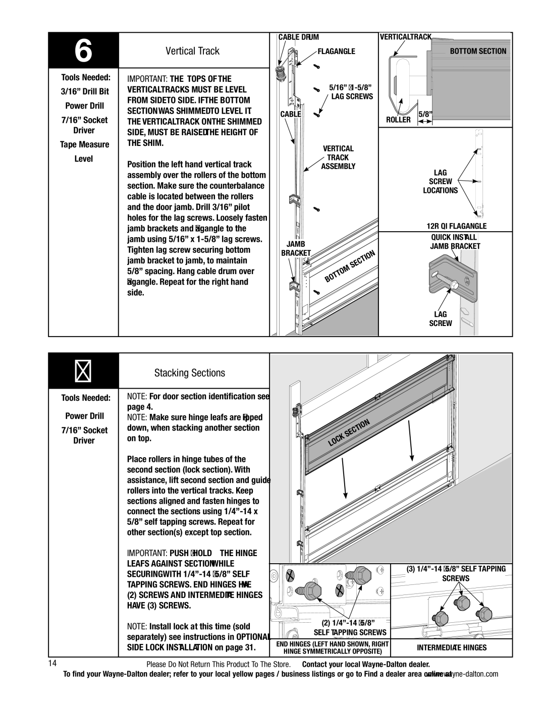
Tools Needed: | IMPORTANT: The tops of the | |
3/16” Drill Bit | vertical tracks must be level | |
Power Drill | from side to side. If the bottom | |
section was shimmed to level it. | ||
7/16” Socket | ||
The vertical track on the shimmed | ||
Driver | side, must be raised the height of | |
Tape Measure | the shim. | |
Level | Position the left hand vertical track | |
| ||
| assembly over the rollers of the bottom | |
| section. Make sure the counterbalance | |
| cable is located between the rollers | |
| and the door jamb. Drill 3/16” pilot | |
| holes for the lag screws. Loosely fasten |
cable drum fLAGANGLE
5/16” x
LAG SCREWS
CABLE
VERTICAL
TRACK
ASSEMBLY
vertical track
BOTTOM SECTION
roller | 5/8” |
|
LAG
SCREW
locations
jamb brackets and flagangle to the |
jamb using 5/16” x |
Tighten lag screw securing bottom |
jamb bracket to jamb, to maintain |
5/8” spacing. Hang cable drum over |
flagangle. Repeat for the right hand |
side. |
JAMB
BRACKET SECTION ![]() BOTTOM
BOTTOM
12r qi flagangle
quick install jamb bracket
lag
screw
|
|
7 | Stacking Sections |
| |
|
|
Tools Needed: | NOTE: For door section identification see |
Power Drill | page 4. |
NOTE: Make sure hinge leafs are flipped | |
7/16” Socket | down, when stacking another section |
Driver | on top. |
| Place rollers in hinge tubes of the |
| second section (lock section). With |
| assistance, lift second section and guide |
| rollers into the vertical tracks. Keep |
| sections aligned and fasten hinges to |
| connect the sections using |
| 5/8” self tapping screws. Repeat for |
| other section(s) except top section. |
SECTION K OC L
| IMPORTANT: Push & hold the hinge |
|
|
| leafs against section while |
| (3) |
| securing with |
| |
|
| SCREWS | |
| tapping screws. End Hinges have |
| |
|
|
| |
| (2) screws and Intermediate hinges |
|
|
| have (3) screws. |
|
|
| NOTE: Install lock at this time (sold | (2) |
|
| SELF TAPPING SCREWS |
| |
| separately) see instructions in OPTIONAL |
| |
| end hinges (left hand shown, right |
| |
| SIDE LOCK INSTALLATION on page 31. | intermediate hinges | |
| hinge symmetrically opposite) | ||
|
|
| |
14 | Please Do Not Return This Product To The Store. Contact your local | ||
| To find your | ||