|
|
| Operator Bracket Continued... |
|
|
|
|
|
| ||
| Tools Needed: |
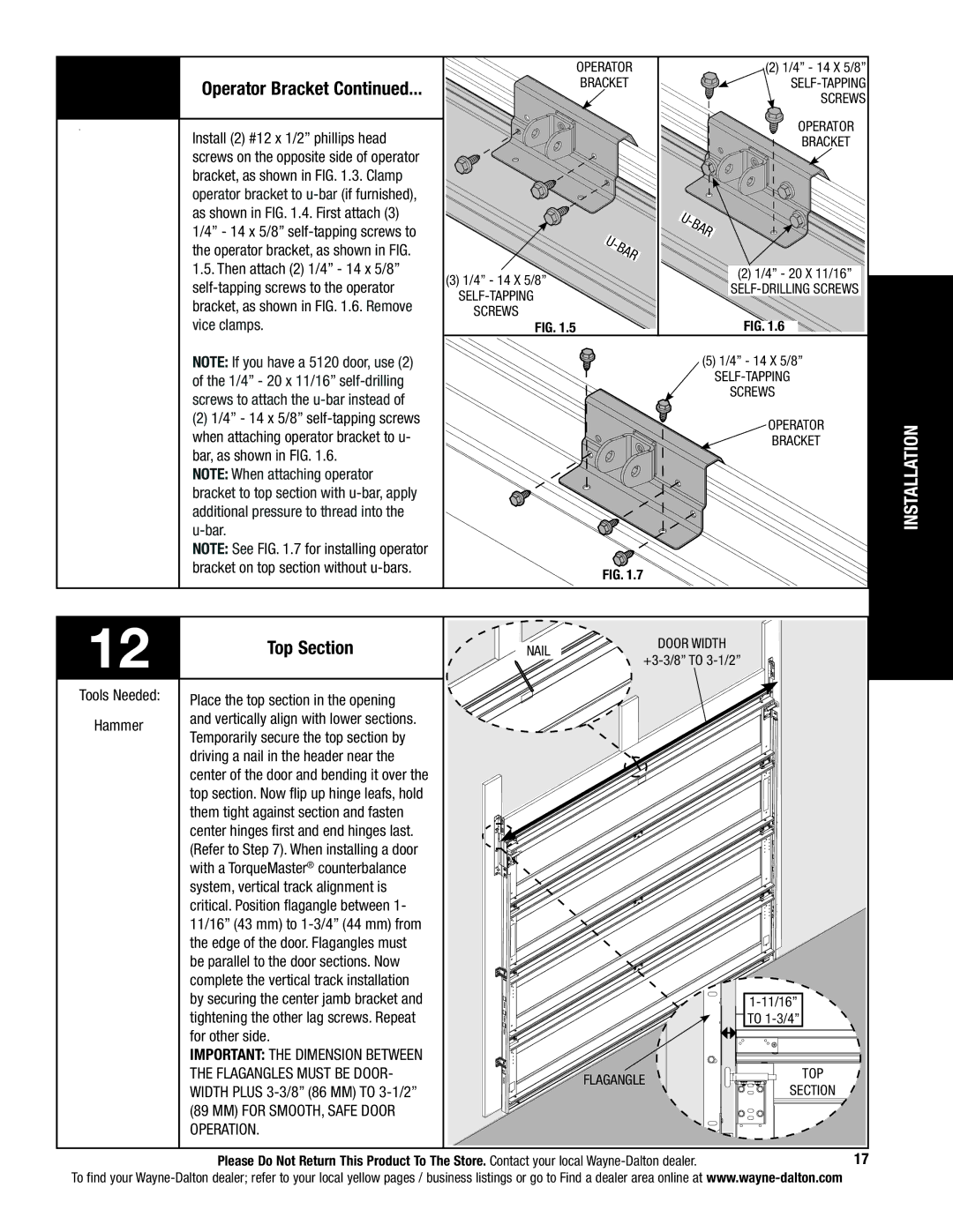
| Install (2) #12 x 1/2” phillips head |
|
|
| screws on the opposite side of operator |
|
|
| bracket, as shown in FIG. 1.3. Clamp |
|
|
| operator bracket to |
|
|
| as shown in FIG. 1.4. First attach (3) |
|
|
| 1/4” - 14 x 5/8” |
|
|
| the operator bracket, as shown in FIG. |
|
|
| 1.5. Then attach (2) 1/4” - 14 x 5/8” |
|
|
| |
|
|
| bracket, as shown in FIG. 1.6. Remove |
|
|
| vice clamps. |
Operator
bracket
|
|
| r |
|
| a | |
| b |
| |
- |
|
| |
U |
|
|
|
(3)1/4” - 14 x 5/8”
screws
FIG. 1.5
(2)1/4” - 14 x 5/8”
Operator
bracket
|
|
| r |
|
| a | |
| b |
| |
- |
|
| |
U |
|
|
|
(2)1/4” - 20 x 11/16”
FIG. 1.6
NOTE: If you have a 5120 door, use (2) of the 1/4” - 20 x 11/16”
(2)1/4” - 14 x 5/8”
NOTE: When attaching operator bracket to top section with
NOTE: See FIG. 1.7 for installing operator bracket on top section without
(5)1/4” - 14 x 5/8”
screws
Operator
bracket
FIG. 1.7
INSTALLATION
12 | Top Section | NAIL | door width |
|
|
|
|
| |
Tools Needed: | Place the top section in the opening |
|
|
|
|
|
|
| |
Hammer | and vertically align with lower sections. |
|
|
|
Temporarily secure the top section by |
|
|
| |
|
|
|
| |
| driving a nail in the header near the |
|
|
|
| center of the door and bending it over the |
|
|
|
| top section. Now flip up hinge leafs, hold |
|
|
|
| them tight against section and fasten |
|
|
|
| center hinges first and end hinges last. |
|
|
|
| (Refer to Step 7). When installing a door |
|
|
|
| with a TorqueMaster® counterbalance |
|
|
|
| system, vertical track alignment is |
|
|
|
| critical. Position flagangle between 1- |
|
|
|
| 11/16” (43 mm) to |
|
|
|
| the edge of the door. Flagangles must |
|
|
|
| be parallel to the door sections. Now |
|
|
|
| complete the vertical track installation |
|
|
|
| by securing the center jamb bracket and |
|
| |
| tightening the other lag screws. Repeat |
|
| TO |
| for other side. |
|
|
|
| IMPORTANT: The dimension between |
|
|
|
| the flagangles must be door- |
| FLAGANGLE | top |
| width plus |
| SECTION | |
|
|
| ||
| (89 mm) for smooth, safe door |
|
|
|
| operation. |
|
|
|
| Please Do Not Return This Product To The Store. Contact your local | 17 | ||
To find your