|
| |
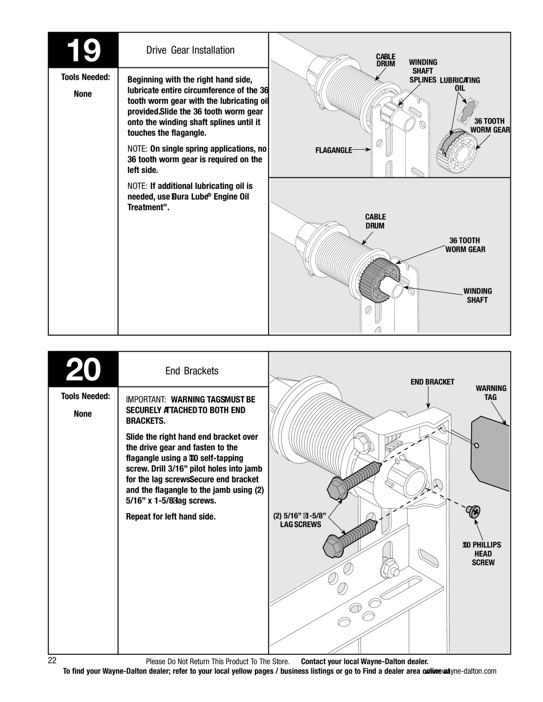
19 | Drive Gear Installation | |
| ||
|
| |
Tools Needed: | Beginning with the right hand side, | |
| ||
None | lubricate entire circumference of the 36 | |
tooth worm gear with the lubricating oil | ||
| ||
| provided. Slide the 36 tooth worm gear | |
| onto the winding shaft splines until it | |
| touches the flagangle. | |
| NOTE: On single spring applications, no | |
| 36 tooth worm gear is required on the | |
| left side. | |
| NOTE: If additional lubricating oil is | |
| needed, use “Dura Lube® Engine Oil | |
| Treatment”. | |
|
|
Cable
Drum Winding Shaft
Splines lubricating oil
36 tooth
worm gear
Flagangle ![]()
Cable
Drum
36 tooth ![]() worm gear
worm gear
![]()
![]() Winding
Winding
Shaft
|
| |
20 | End Brackets | |
| ||
|
| |
Tools Needed: | IMPORTANT: Warning Tags must be | |
| ||
None | securely attached to both End | |
Brackets. | ||
| ||
| Slide the right hand end bracket over | |
| the drive gear and fasten to the | |
| flagangle using a #10 | |
| screw. Drill 3/16” pilot holes into jamb | |
| for the lag screws. Secure end bracket | |
| and the flagangle to the jamb using (2) | |
| 5/16” x | |
| Repeat for left hand side. |
End Bracket
(2) 5/16” x ![]() Lag Screws
Lag Screws
Warning
Tag
#10 Phillips
Head
Screw
22Please Do Not Return This Product To The Store. Contact your local
To find your