23 | Positioning Support Bracket | TorqueMaster® | 45 angle |
|
| Mounting |
spring tube |
|
| ||||
Antenna | surface | |||||
|
|
|
| |||
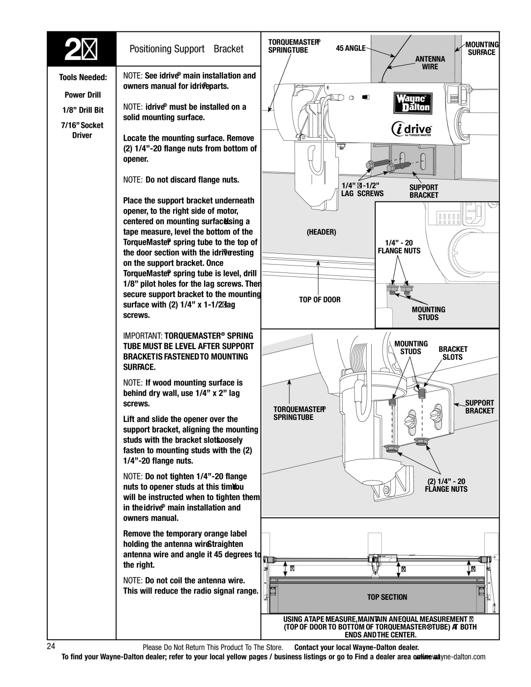
| NOTE: See idrive® main installation and |
|
| wire |
|
|
Tools Needed: |
|
|
|
|
| |
Power Drill | owners manual for idrive® parts. |
|
|
|
|
|
|
|
|
|
|
| |
1/8” Drill Bit | NOTE: idrive® must be installed on a |
|
|
|
|
|
solid mounting surface. |
|
|
|
|
| |
7/16” Socket |
|
|
|
|
| |
|
|
|
|
|
| |
Driver | Locate the mounting surface. Remove |
|
|
|
|
|
|
|
|
|
|
| |
| (2) |
|
|
|
|
|
| opener. |
|
|
|
|
|
| NOTE: Do not discard flange nuts. |
| 1/4” X | SUPPORT |
|
|
|
|
|
|
| ||
| Place the support bracket underneath |
| LAG SCREWs | BRACKET |
|
|
|
|
|
|
|
| |
| opener, to the right side of motor, |
|
|
|
|
|
| centered on mounting surface. Using a |
|
|
|
|
|
| tape measure, level the bottom of the | (Header) |
|
|
|
|
| TorqueMaster® spring tube to the top of |
|
| 1/4” - 20 |
|
|
| the door section with the idrive® resting |
| FLANGE NUTS |
|
| |
| on the support bracket. Once |
|
|
|
|
|
| TorqueMaster® spring tube is level, drill |
|
|
|
|
|
| 1/8” pilot holes for the lag screws. Then |
|
|
|
|
|
| secure support bracket to the mounting | TOP OF DOOR |
|
|
| |
| surface with (2) 1/4” x |
|
|
| ||
|
|
| Mounting |
| ||
| screws. |
|
|
| ||
|
|
| studs |
|
| |
| IMPORTANT: TorqueMaster® spring |
|
| Mounting |
|
|
| tube must be level after support |
|
| Bracket | ||
| bracket is fastened to mounting |
|
| studs | ||
|
|
| slots |
| ||
|
|
|
|
| ||
| surface. |
|
|
|
|
|
| NOTE: If wood mounting surface is |
|
|
|
|
|
| behind dry wall, use 1/4” x 2” lag |
|
|
|
|
|
| screws. | TorqueMaster® |
|
|
| support |
|
|
|
|
| bracket | |
| Lift and slide the opener over the | spring tube |
|
|
|
|
| support bracket, aligning the mounting |
|
|
|
|
|
| studs with the bracket slots. Loosely |
|
|
|
|
|
| fasten to mounting studs with the (2) |
|
|
|
|
|
|
|
|
|
|
| |
| NOTE: Do not tighten |
|
| (2) 1/4” - 20 |
| |
| nuts to opener studs at this time. You |
|
|
| ||
|
|
| flange nuts | |||
| will be instructed when to tighten them |
|
|
|
|
|
| in the idrive® main installation and |
|
|
|
|
|
| owners manual. |
|
|
|
|
|
| Remove the temporary orange label |
|
|
|
|
|
| holding the antenna wire. Straighten |
|
|
|
|
|
| antenna wire and angle it 45 degrees to |
|
|
|
|
|
| the right. | “x” |
| “x” |
| “x” |
|
|
|
| |||
| NOTE: Do not coil the antenna wire. |
|
|
|
|
|
| This will reduce the radio signal range. |
| top section |
|
| |
|
|
|
|
| ||
|
| Using a tape measure, maintain an equal measurement “x” | ||||
|
| (top of door to bottom of Torquemaster® tube) at both | ||||
|
|
| ends and the center. |
|
| |
24 | Please Do Not Return This Product To The Store. Contact your local |
|
| |||
To find your