� |
| Trolley Operator | |
|
| ||
|
|
|
|
|
|
|
|
Tools Needed: |
| WARNING | |
OPERATOR MUST BE TESTED AT TIME
OF INSTALLATION AND MONTHLY
THEREAFTER TO ENSURE THAT DOOR
REVERSES ON CONTACT WITH 2 X 4
BOARD LAID FLAT UNDER THE DOOR.
FAILURE TO ADJUST OPERATOR,
IF NECESSARY, CAN RESULT IN
SEVERE OR FATAL INJURY. IF YOUR
OPERATOR IS EQUIPPED WITH A
PHOTOELECTRIC EYE SYSTEM, THEN
THIS MUST BE TESTED AT THE SAME
TIME TO ENSURE THAT DOOR DOES
NOT CLOSE AND A CLOSING DOOR
OPENS IF PHOTOELECTRIC EYE SYSTEM
IS OBSTRUCTED. FAILURE TO MAKE
ADJUSTMENTS, IF NECESSARY, CAN
RESULT IN SEVERE OR FATAL INJURY.
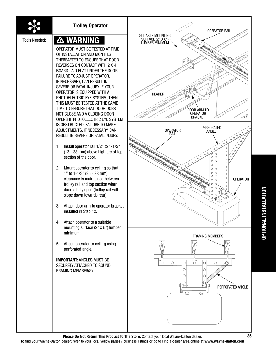
1.Install operator rail 1/2” to
2.Mount operator to ceiling so that 1” to
3.Attach door arm to operator bracket installed in Step 12.
4.Attach operator to a suitable mounting surface (2” x 6”) lumber minimum.
5.Attach operator to ceiling using perforated angle.
IMPORTANT: Angles must be securely attached to sound framing member(s).
OPERATOR RAIL
Suitable mounting
surface (2” x 6”) lumber minimum
header
door arm to
operator
bracket
perforated
OPERATORangle rail
OPERATOR
FRAMING MEMBERS
PERFORATED ANGLE
OPTIONAL INSTALLATION
Please Do Not Return This Product To The Store. Contact your local | 35 |
To find your