�Trolley Installation for
Low Headroom
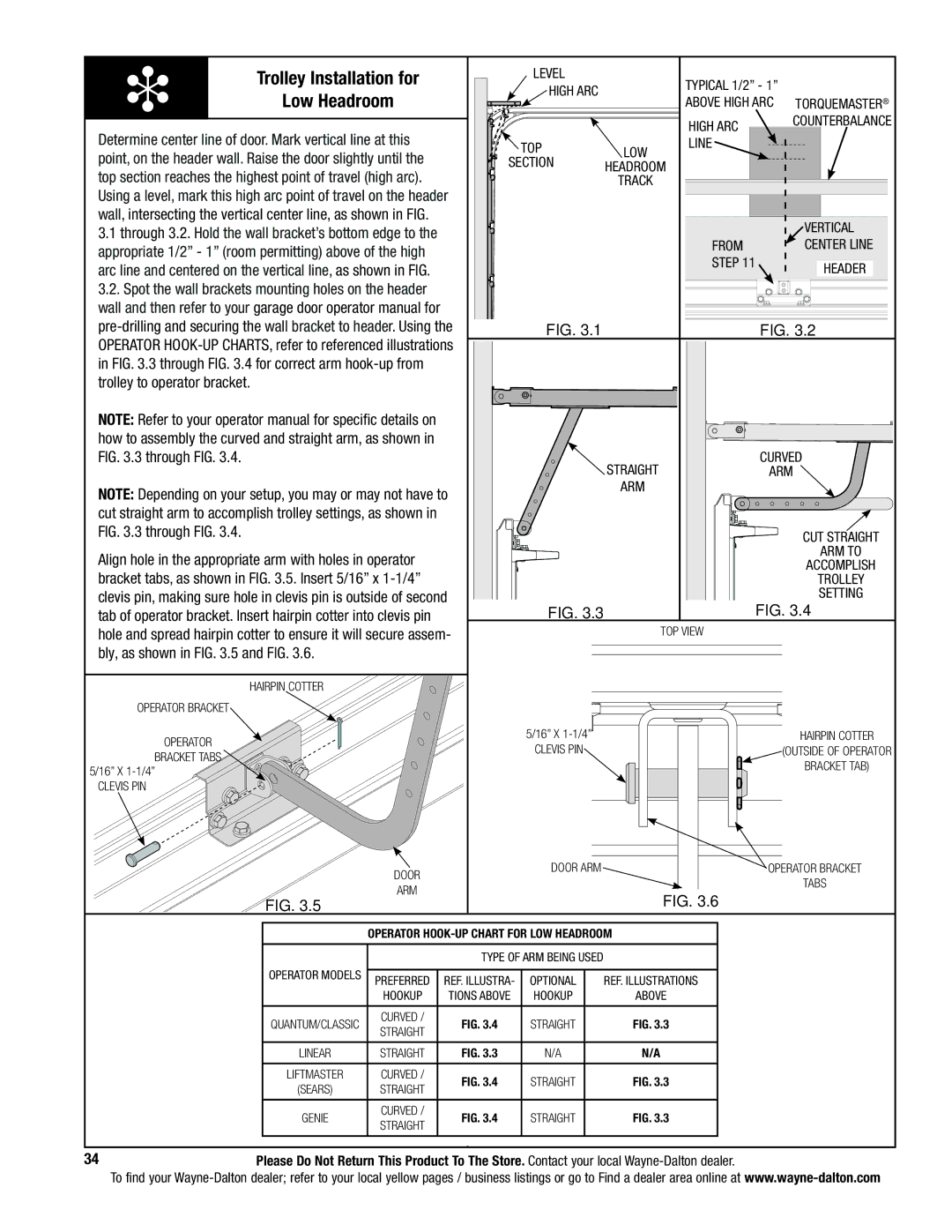
Determine center line of door. Mark vertical line at this point, on the header wall. Raise the door slightly until the top section reaches the highest point of travel (high arc). Using a level, mark this high arc point of travel on the header wall, intersecting the vertical center line, as shown in FIG.
3.1through 3.2. Hold the wall bracket’s bottom edge to the appropriate 1/2” - 1” (room permitting) above of the high arc line and centered on the vertical line, as shown in FIG.
3.2.Spot the wall brackets mounting holes on the header wall and then refer to your garage door operator manual for
NOTE: Refer to your operator manual for specific details on how to assembly the curved and straight arm, as shown in FIG. 3.3 through FIG. 3.4.
NOTE: Depending on your setup, you may or may not have to cut straight arm to accomplish trolley settings, as shown in FIG. 3.3 through FIG. 3.4.
Align hole in the appropriate arm with holes in operator bracket tabs, as shown in FIG. 3.5. Insert 5/16” x
Hairpin Cotter
Operator Bracket
Operator
Bracket tabs 5/16” x
Clevis pin
Door
Arm
FIG. 3.5
Level |
| Typical 1/2” - 1” |
|
HIGH ARC |
|
| |
| above high arc | Torquemaster® | |
|
| ||
|
| HIGH ARC | Counterbalance |
|
|
| |
TOP | Low | line |
|
|
| ||
SECTION |
|
| |
headroom |
|
| |
| track |
|
|
|
|
| Vertical |
|
| From | center line |
|
| step 11 | Header |
|
|
|
FIG. 3.1 | FIG. 3.2 |
Straight | CURVED |
arm | |
arm |
|
Cut Straight
arm to
accomplish
trolley setting
FIG. 3.3 | FIG. 3.4 |
| Top view |
5/16” x | Hairpin Cotter |
Clevis pin | (Outside of operator |
| bracket tab) |
Door arm | Operator bracket |
| tabs |
FIG. 3.6
Operator
|
| Type of arm Being used |
| ||
Operator models |
|
|
|
|
|
PREFERRED | Ref. Illustra- | Optional |
| Ref. Illustrations | |
|
| ||||
| hookup | tions above | hookup |
| above |
|
|
|
|
|
|
Quantum/classic | Curved / | Fig. 3.4 | STRAIGHT |
| Fig. 3.3 |
Straight |
| ||||
|
|
|
|
| |
|
|
|
|
|
|
Linear | Straight | Fig. 3.3 | N/A |
| N/a |
|
|
|
|
|
|
Liftmaster | Curved / | Fig. 3.4 | STRAIGHT |
| Fig. 3.3 |
(sears) | Straight |
| |||
|
|
|
| ||
|
|
|
|
|
|
Genie | Curved / | Fig. 3.4 | STRAIGHT |
| Fig. 3.3 |
Straight |
| ||||
|
|
|
|
| |
|
|
|
|
|
|
34Please Do Not Return This Product To The Store. Contact your local
To find your