PREINSTALLATION
Tables
The relatively small dimensions of the DocuPrint 96/DocuPrint 96MX system controller and the optional peripheral cabinet are not likely to be of concern during delivery. Refer to figures
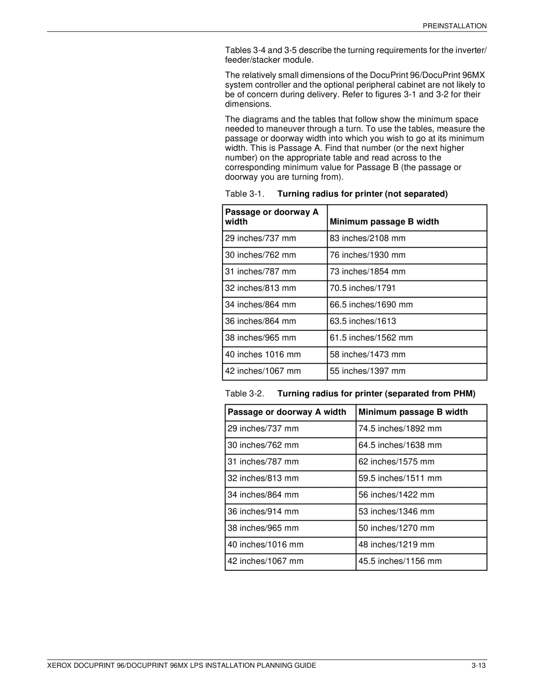
The diagrams and the tables that follow show the minimum space needed to maneuver through a turn. To use the tables, measure the passage or doorway width into which you wish to go at its minimum width. This is Passage A. Find that number (or the next higher number) on the appropriate table and read across to the corresponding minimum value for Passage B (the passage or doorway you are turning from).
Table
Passage or doorway A |
|
width | Minimum passage B width |
|
|
29 inches/737 mm | 83 inches/2108 mm |
|
|
30 inches/762 mm | 76 inches/1930 mm |
|
|
31 inches/787 mm | 73 inches/1854 mm |
|
|
32 inches/813 mm | 70.5 inches/1791 |
|
|
34 inches/864 mm | 66.5 inches/1690 mm |
|
|
36 inches/864 mm | 63.5 inches/1613 |
|
|
38 inches/965 mm | 61.5 inches/1562 mm |
|
|
40 inches 1016 mm | 58 inches/1473 mm |
|
|
42 inches/1067 mm | 55 inches/1397 mm |
|
|
Table
Passage or doorway A width | Minimum passage B width |
|
|
29 inches/737 mm | 74.5 inches/1892 mm |
|
|
30 inches/762 mm | 64.5 inches/1638 mm |
|
|
31 inches/787 mm | 62 inches/1575 mm |
|
|
32 inches/813 mm | 59.5 inches/1511 mm |
|
|
34 inches/864 mm | 56 inches/1422 mm |
|
|
36 inches/914 mm | 53 inches/1346 mm |
|
|
38 inches/965 mm | 50 inches/1270 mm |
|
|
40 inches/1016 mm | 48 inches/1219 mm |
|
|
42 inches/1067 mm | 45.5 inches/1156 mm |
|
|
XEROX DOCUPRINT 96/DOCUPRINT 96MX LPS INSTALLATION PLANNING GUIDE |
