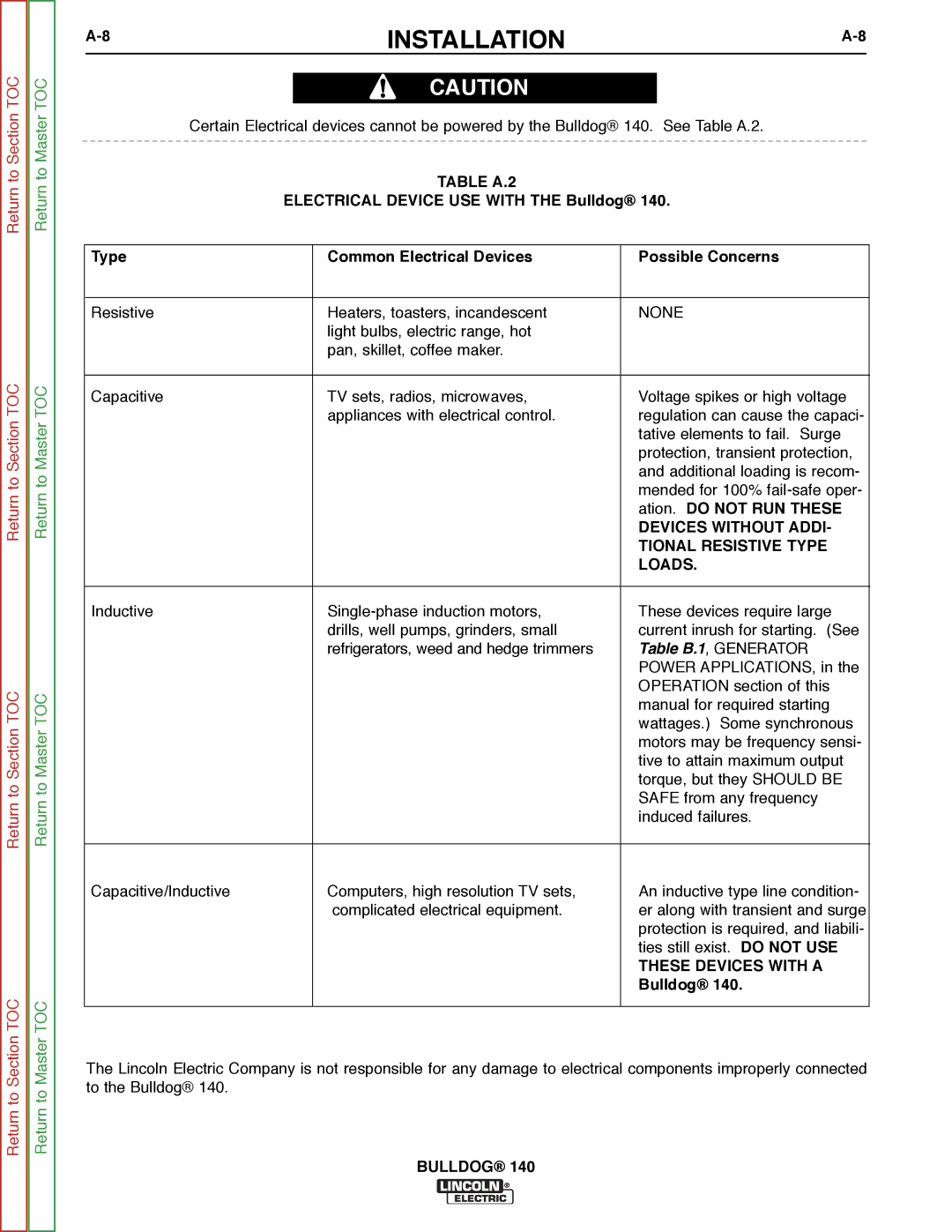
Lincoln Electric SVM208-A Stacking, Tilting, Oil, Fuel, Lifting, PRE-OPERATION Engine Service

Page 12

A-4

INSTALLATION

A-4


Return to Master TOC

STACKING

Bulldog® 140 machines CANNOT be stacked.

TILTING

Place the machine on a secure, level surface whenev- er you use it or store it. Any surfaces you place it on other than the ground must be firm, non-skid, and structurally sound.

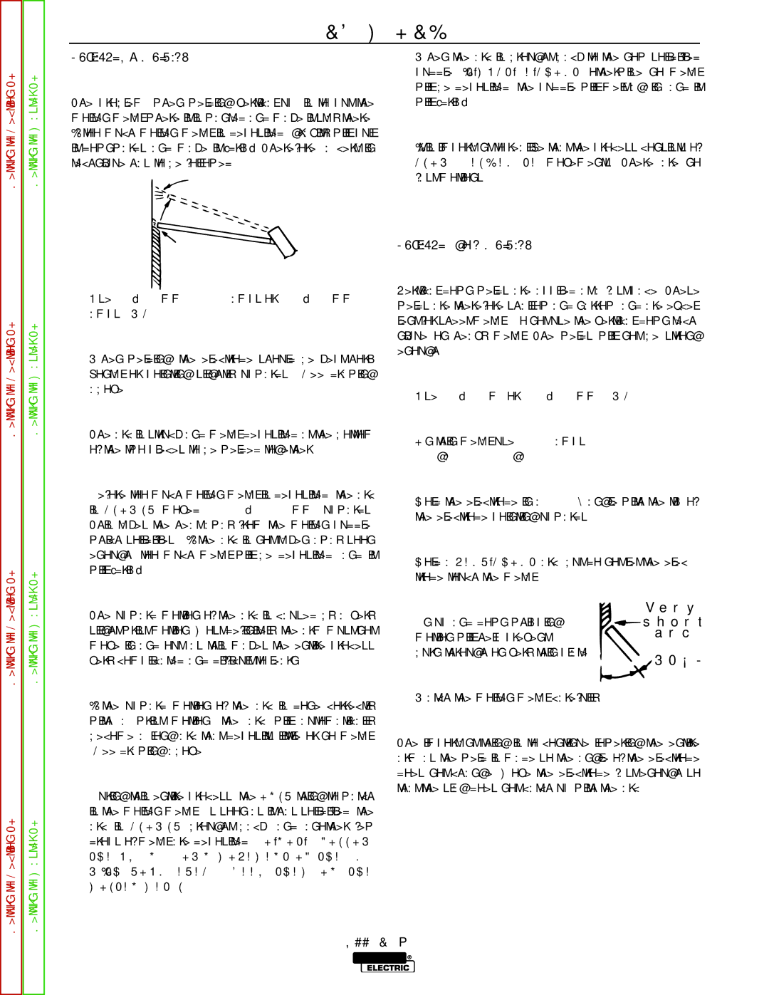
The gasoline engine is designed to run in a level posi- tion for best performance. It can operate at an angle, but this should never be more than 15 degrees in any direction. If you do operate it at a slight angle, be sure to check the oil regularly and keep the oil level full. Also, fuel capacity will be a little less at an angle.

OIL

The Bulldog® 140 is shipped with the engine filled with SAE 10W30 oil. CHECK THE OIL LEVEL BEFORE YOU START THE ENGINE. This is an added precau- tion. Do not screw in dipstick when checking oil level. DO NOT OVERFILL. Be sure the fill plug is tight after servicing.

FUEL

Fill the fuel tank with clean, fresh, regular grade (mini- mum 87 octane lead free gasoline. DO NOT MIX OIL WITH GAS. The Bulldog® 140 capacity is approxi- mately 6.8 gallons (25.74 Liter). DO NOT OVERFILL, allow room in the fuel tank for fuel expansion.

Return to Section TOC

Return to Section TOC

Return to Section TOC

Return to Section TOC

Return to Master TOC

Return to Master TOC

Return to Master TOC

LIFTING

The Bulldog® 140 should be lifted by two people. (See Specification section for weight). The LowLift™ grab bars on both ends make lifting easier.

PRE-OPERATION ENGINE SERVICE

Read and understand the engine operating and maintenance instructions supplied with this machine before you operate the Bulldog® 140.

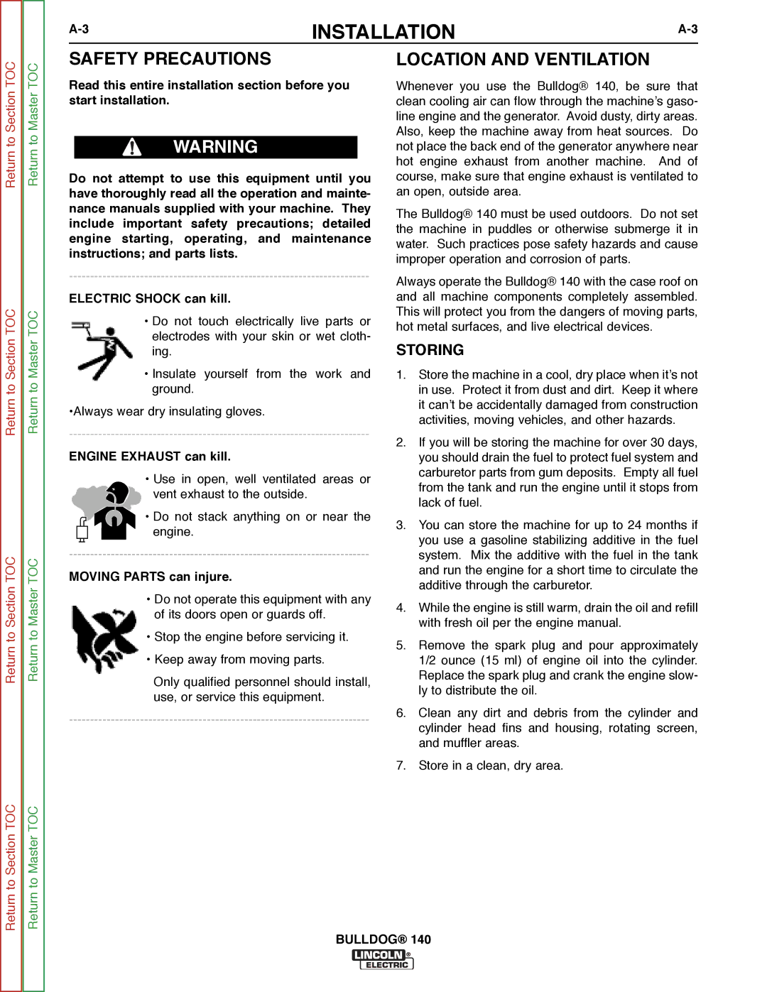
WARNING

Keep hands away from muffler or HOT engine parts.

Stop the engine when fueling.

Do not smoke when fueling.

Remove fuel cap slowly to release pressure.

Do not overfill tank.

Wipe up spilled fuel and allow fumes to clear before starting engine.

Keep sparks and flame away from tank.

------------------------------------------------------------------------

SPARK ARRESTER

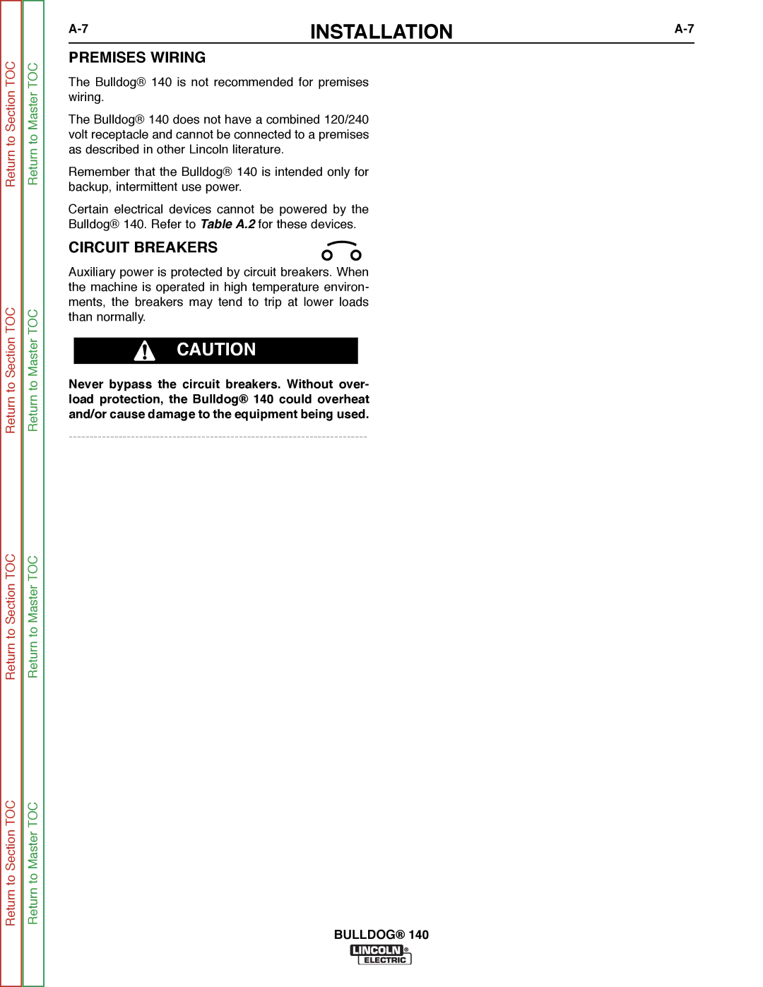
Some federal, state or local laws may require gasoline engines to be equipped with exhaust spark arresters when they are operated in certain locations where unarrested sparks may present a fire hazard. The standard muffler included with this machine does qual- ify as a spark arrester.

Bulldog® 140 Typical Fuel Consumption


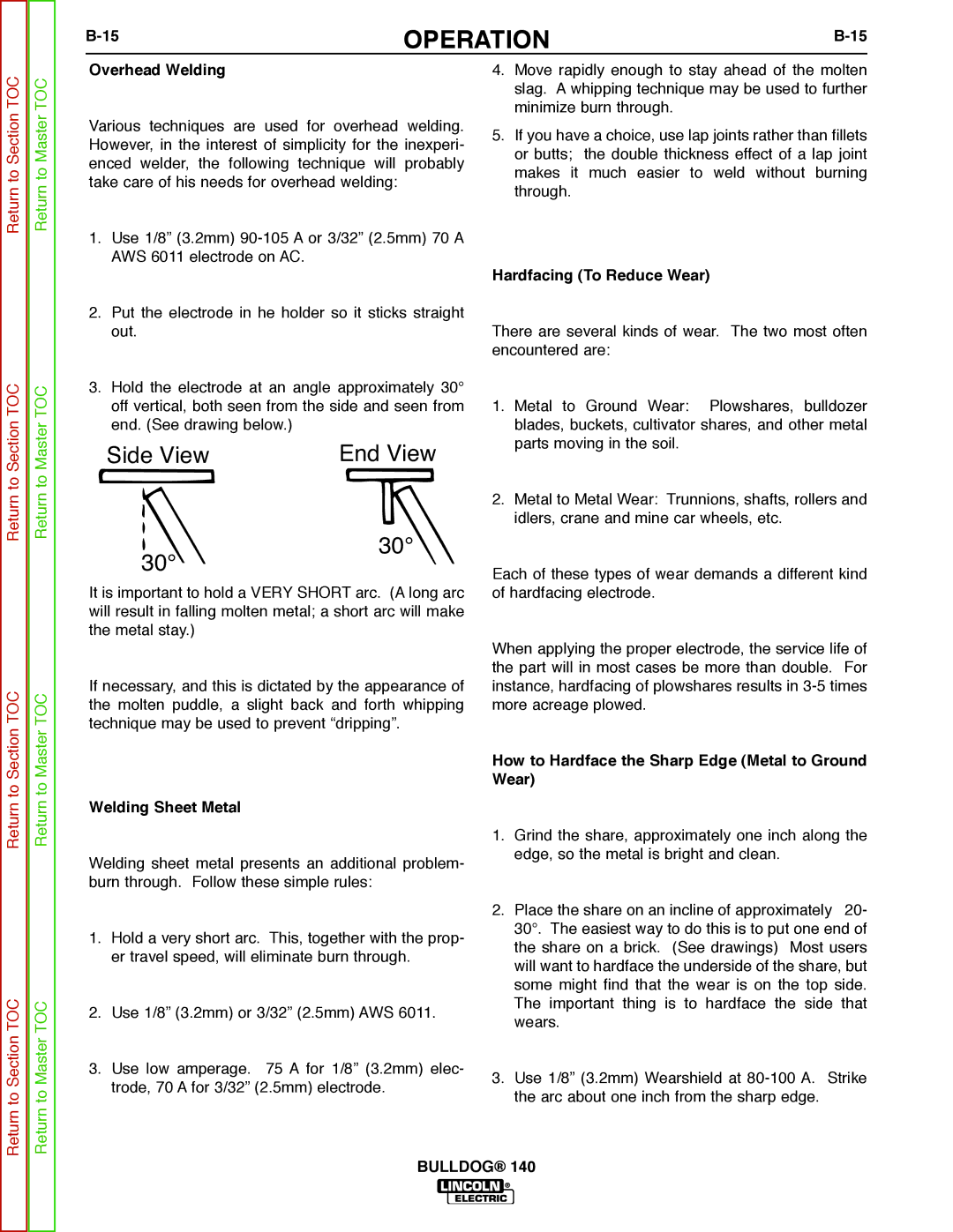
Robin / Subaru 10 HP Carb.


Certified EX 30


No Load

.31 Gallons/Hour

3750 RPM ±100 R.P.M.

(1.16 Liters/Hour)


AC CC Weld Output

.53 Gallons/Hour

80 Amps @ 25 Volts

(2.02 Liters/Hour)


Auxiliary Power 4000

.70 Gallons/Hour

Watts (120/240 Volts)

(2.65 Liters/Hour)


BULLDOG® 140
Image 12
Contents Bulldog Safety California Proposition 65 WarningsElectric Shock can kill ARC Rays can burn Can be dangerousWelding and Cutting Sparks can cause fire or explosion Cylinder may explode if damagedIii Précautions DE Sûreté Sûreté Pour Soudage a L’ArcSafety Methods of Reducing Emissions Mains Supply Master Table of Contents for ALL Sections Table of Contents Installation Section Installation Technical Specifications Bulldog 140 K2708-1Safety Precautions Location and VentilationStoring Engine Exhaust can killPRE-OPERATION Engine Service StackingTilting OILElectrical Output CONNEC- Tions Welding Cable ConnectionsTable A.1 Recommended Welding Cable Size and Length Auxiliary Power Receptacles Cable InstallationElectrical Connections Plugs and HAND-HELD EquipmentPremises Wiring Circuit BreakersAtion. do not RUN These BulldogTable of Contents Operation Section Operation Limitations WELDER/GENERATOR ControlsOutput Panel Controls Engine Operation Gasoline Engine ControlsBefore Starting the Engine Starting the EngineGenerator Operation Table B.1 Generator Power Applications Welding Operation Control Function / OperationMaterial Thickness Electrode Type Size Setting Welding GuidelinesStick Welding Learning To Stick WeldWhat Happens in the Arc? Correct Welding Position Side viewPractice Use the followingDo the following Butt JointsFillet Joints PenetrationVertical-Up Welding Vertical-Down WeldingHow to Hardface the Sharp Edge Metal to Ground Wear Overhead WeldingWelding Sheet Metal Hardfacing To Reduce WearWelding Cast Iron Cast Iron Plate PreparationHigh-Speed Group AWS E6013 Low Hydrogen Group AWS E7018Out-of-Position Group AWS E6011 Bulldog Table of Contents Accessories Section Accessories OPTIONS/ACCESSORIESLincoln Electric Accessories Table of Contents Maintenance Section Maintenance Routine and Periodic Maintenance Engine MaintenanceLocation Engine Adjustments Return to Section TOC To Section TOCTable D.1 Engine Maintenance Parts Spark Plug ServiceOperational Clearance GENERATOR/WELDER Maintenance Screws BrushesFigure D.7. Major Component Locations Bulldog 1TABLE of CONTENTS-THEORY of Operation Section E-1 Theory of Operation ENGINE, EXCITATION, Rotor StatorRotor Field Feedback Auxiliary Power Figure E.3 Rotor Field Feedback and Auxiliary PowerAuxiliary Power Overcurrent Protection Weld Winding and Reactor1TABLE of Contents Troubleshooting and Repair F-1 Troubleshooting and Repair HOW to USE Troubleshooting GuidePC Board Troubleshooting Procedures Output Problems Electric Authorized Field Ser vice Facility Perform the Rotor Voltage TestProblems Symptoms Troubleshooting and Repair Perform Field Diode Test Engine Problems Troubleshooting and Repair Engine Throttle Adjustment Test Bulldog Rotor Voltage Test Test DescriptionMaterials Needed Procedure Rotor Voltage TestLead 200A Connection Ground Stud Field Diode Bridge Test Field Diode Bridge Test + ~Rotor Flashing Circuit Test Rotor Flashing Circuit Test Figure F.3 Brush Holder Leads 201- and 202B +Moving Parts can injure Bulldog Rotor Resistance Test Rotor Resistance Test Cable TIE Brushes Figure F.6 Brushes Retained with Cable TIEBulldog Engine Throttle Adjustment Test ROBIN/SUBARU Engine Engine Throttle Adjustment Test ROBIN/SUBARU EngineStrobe-tach Method Frequency Counter MethodHigh Speed Stop Screw Scope Settings Normal Open Circuit Voltage Waveform 115VAC Supply High Idle no LoadTypical Weld Output Waveform Machine LoadedMachine Loaded to 125 Amps AT 23 VAC Brush Removal and Replacement Brush Removal and Replacement Cable TIE BrushesReturn to Section Return to Section TOC Bulldog Rheostat Removal and Replacement Rheostat Removal and Replacement Figure F.11 Rheostat RemovalCapacitor AND/OR Diode Bridge Removal and Replacement Removal and Replacement Procedure Capacitor Removal and ReplacementCapacitor AND/OR Diode Bridge Procedure Field Diode Bridge Removal and Replacement Figure F.13 Field Diode Bridge LocationBulldog STATOR/ROTOR Removal and Replacement InstructionsSTATOR/ROTOR Removal and Replacement GeneratorengineFigure F.15 Generator Components Troubleshooting and Repair Stator Removal Procedure Figure F.16 Output Lead Location TIE Wrap TerminalsThru Bolts Support NutsRotor Removal Procedure Reassembly ProcedureFigure F.19 Checking ROTOR-STATOR AIR GAP Auxiliary Power Receptacle OUTPUT1 Retest After RepairEngine Output WELDER/GENERATOR OUTPUT1Bulldog Table of Contents Diagram Section Wiring Diagram Bulldog S28101