Lincoln Electric SVM208-A service manual Problems Symptoms

Page 54

F-6

TROUBLESHOOTING AND REPAIR

F-6


Observe Safety Guidelines detailed in the beginning of this manual.

Return to Section TOC

Return to Section TOC

Return to Section TOC

Return to Master TOC

Return to Master TOC

Return to Master TOC

PROBLEMS

(SYMPTOMS)

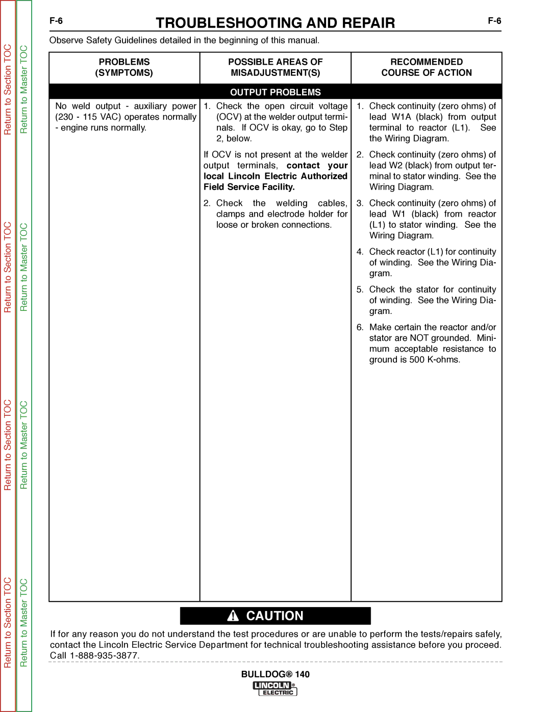
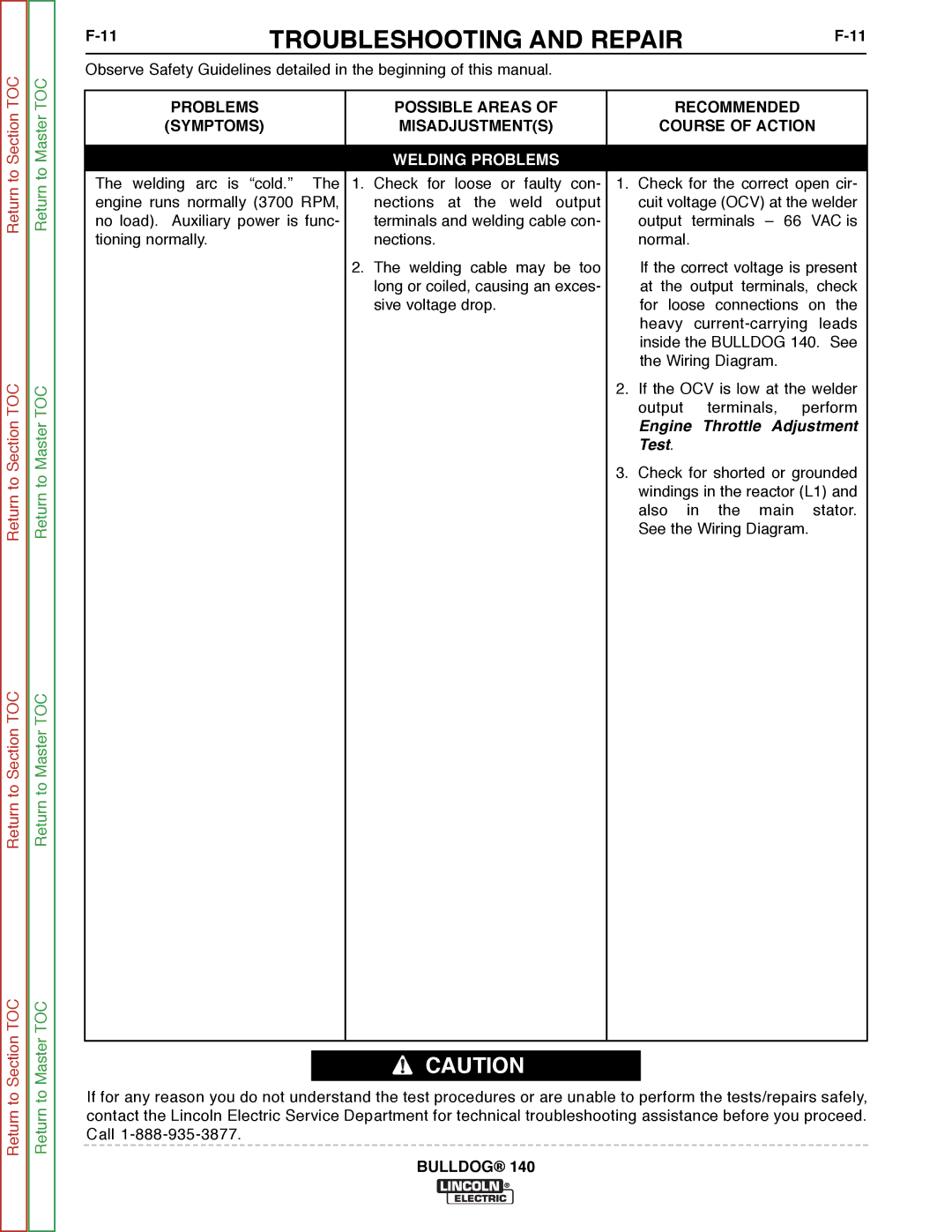
No weld output - auxiliary power (230 - 115 VAC) operates normally - engine runs normally.

POSSIBLE AREAS OF

MISADJUSTMENT(S)

OUTPUT PROBLEMS

1.Check the open circuit voltage (OCV) at the welder output termi- nals. If OCV is okay, go to Step 2, below.

If OCV is not present at the welder output terminals, contact your local Lincoln Electric Authorized Field Service Facility.

2.Check the welding cables, clamps and electrode holder for loose or broken connections.

RECOMMENDED

COURSE OF ACTION

1.Check continuity (zero ohms) of lead W1A (black) from output terminal to reactor (L1). See the Wiring Diagram.

2.Check continuity (zero ohms) of lead W2 (black) from output ter- minal to stator winding. See the Wiring Diagram.

3.Check continuity (zero ohms) of lead W1 (black) from reactor (L1) to stator winding. See the Wiring Diagram.

4.Check reactor (L1) for continuity of winding. See the Wiring Dia- gram.

5.Check the stator for continuity of winding. See the Wiring Dia- gram.

6.Make certain the reactor and/or stator are NOT grounded. Mini- mum acceptable resistance to ground is 500 K-ohms.

Return to Section TOC

Return to Master TOC

CAUTION

If for any reason you do not understand the test procedures or are unable to perform the tests/repairs safely, contact the Lincoln Electric Service Department for technical troubleshooting assistance before you proceed. Call 1-888-935-3877.
BULLDOG® 140

Image 54
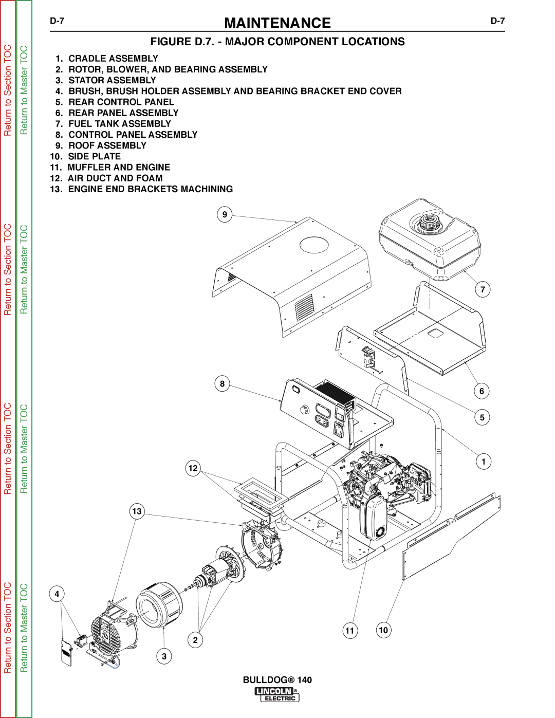
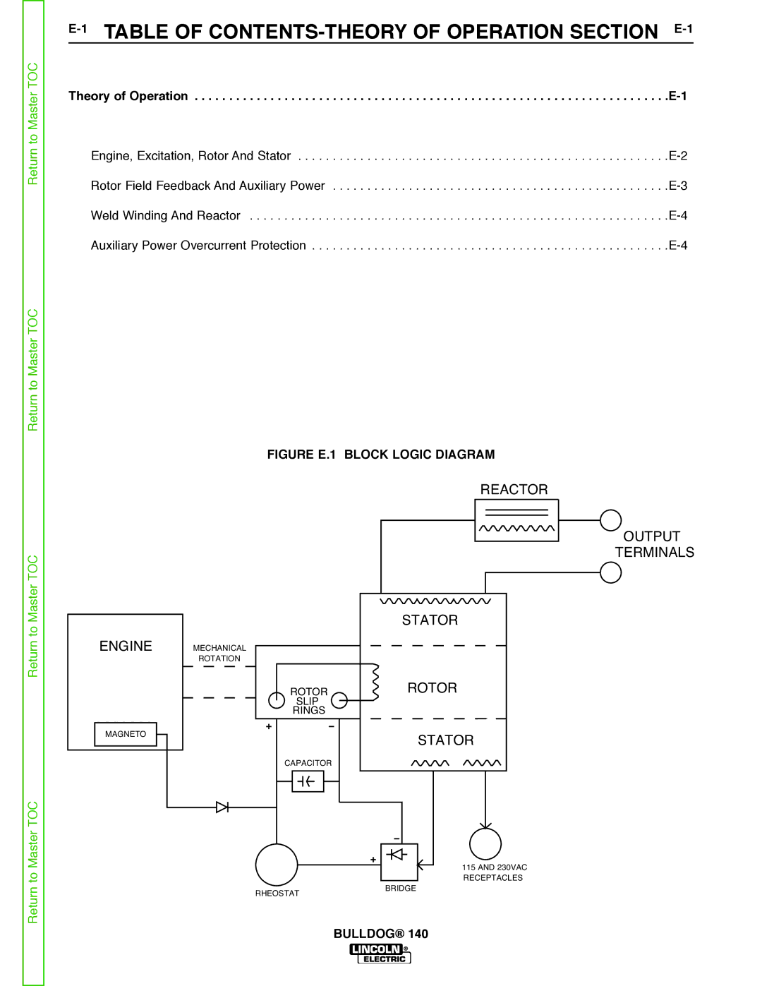
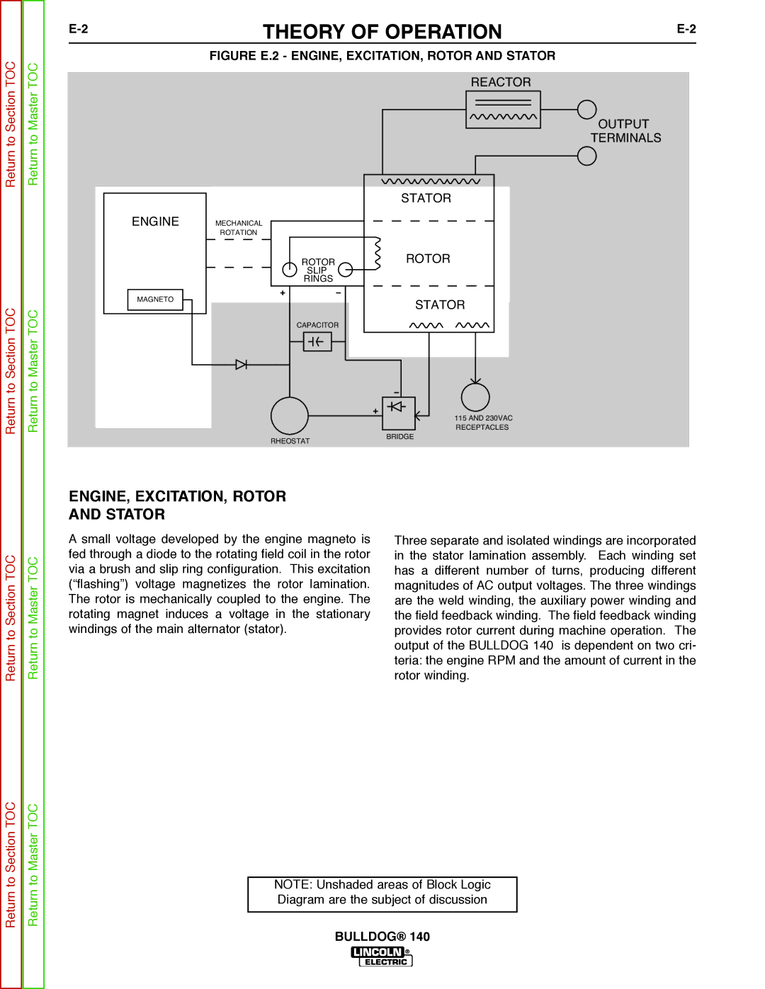
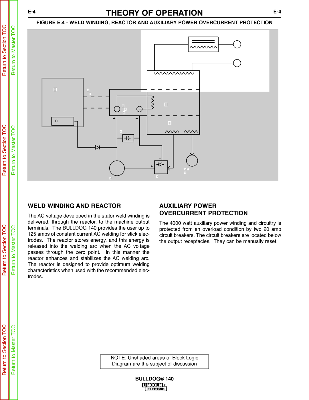
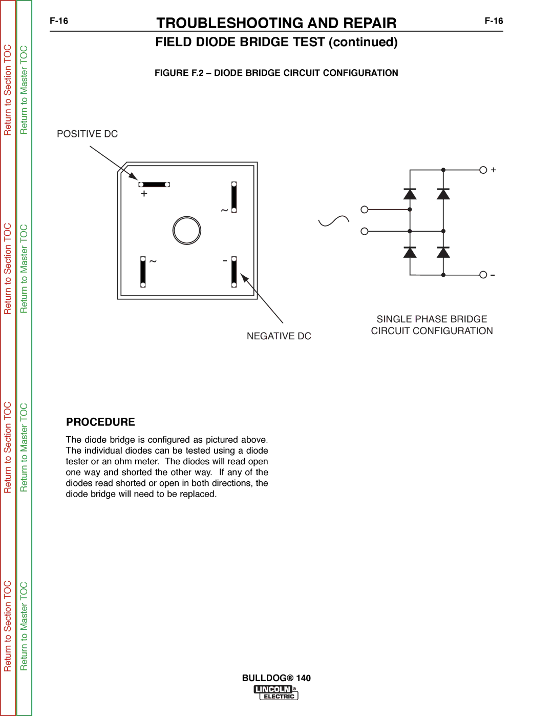
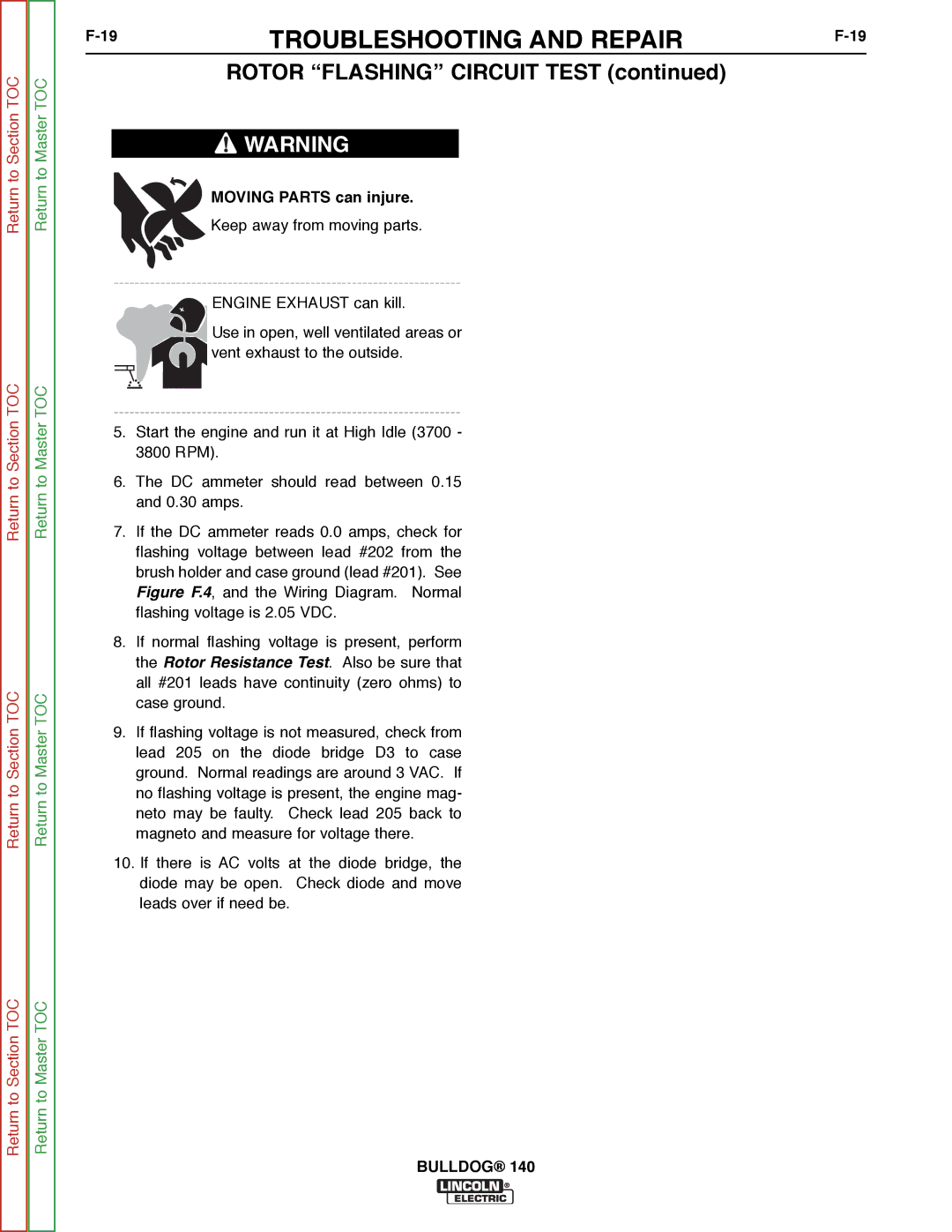
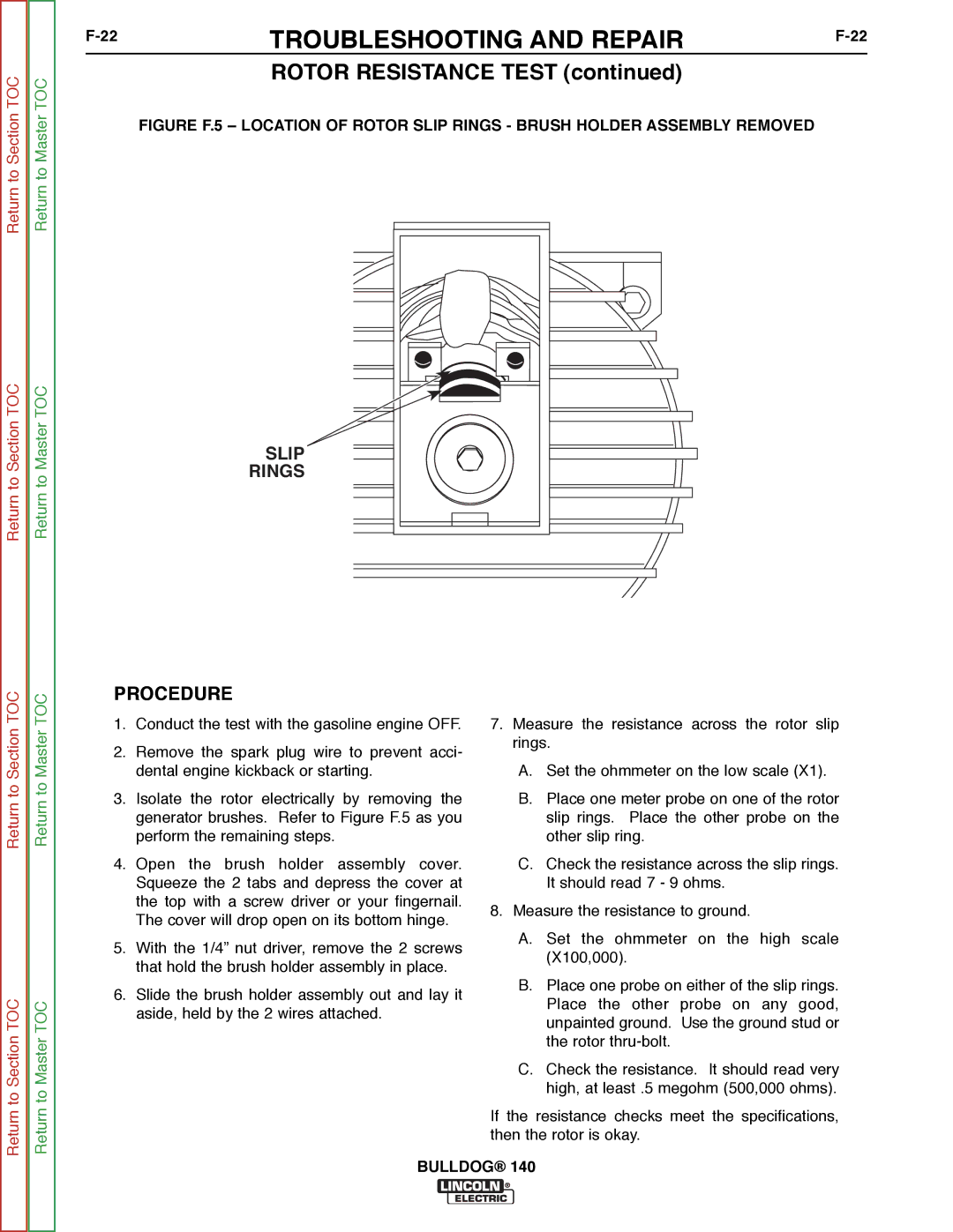
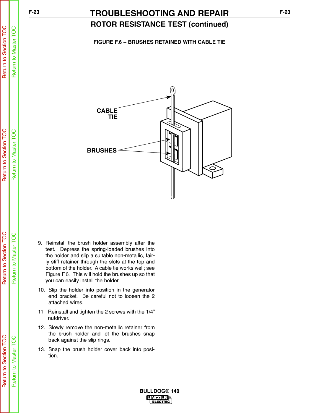
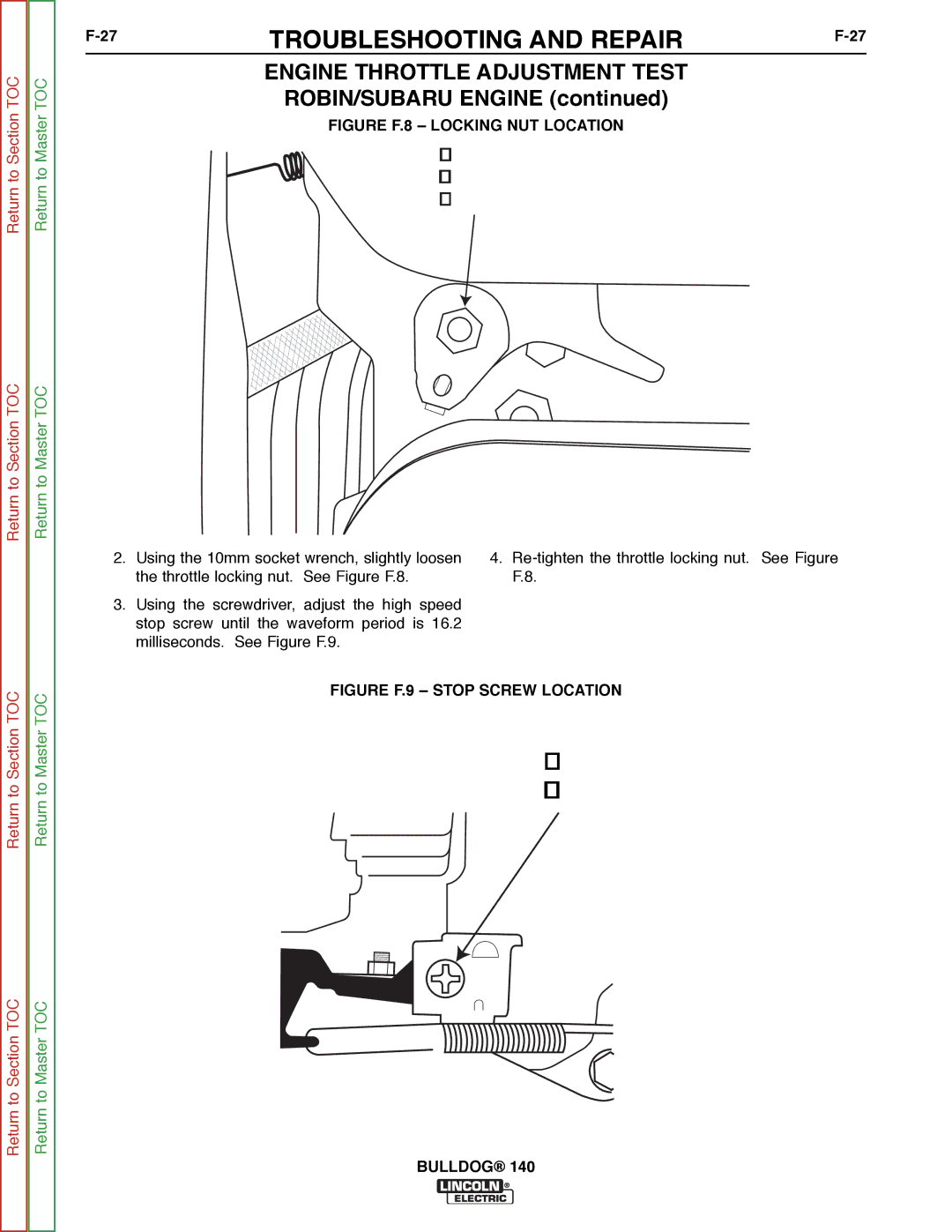
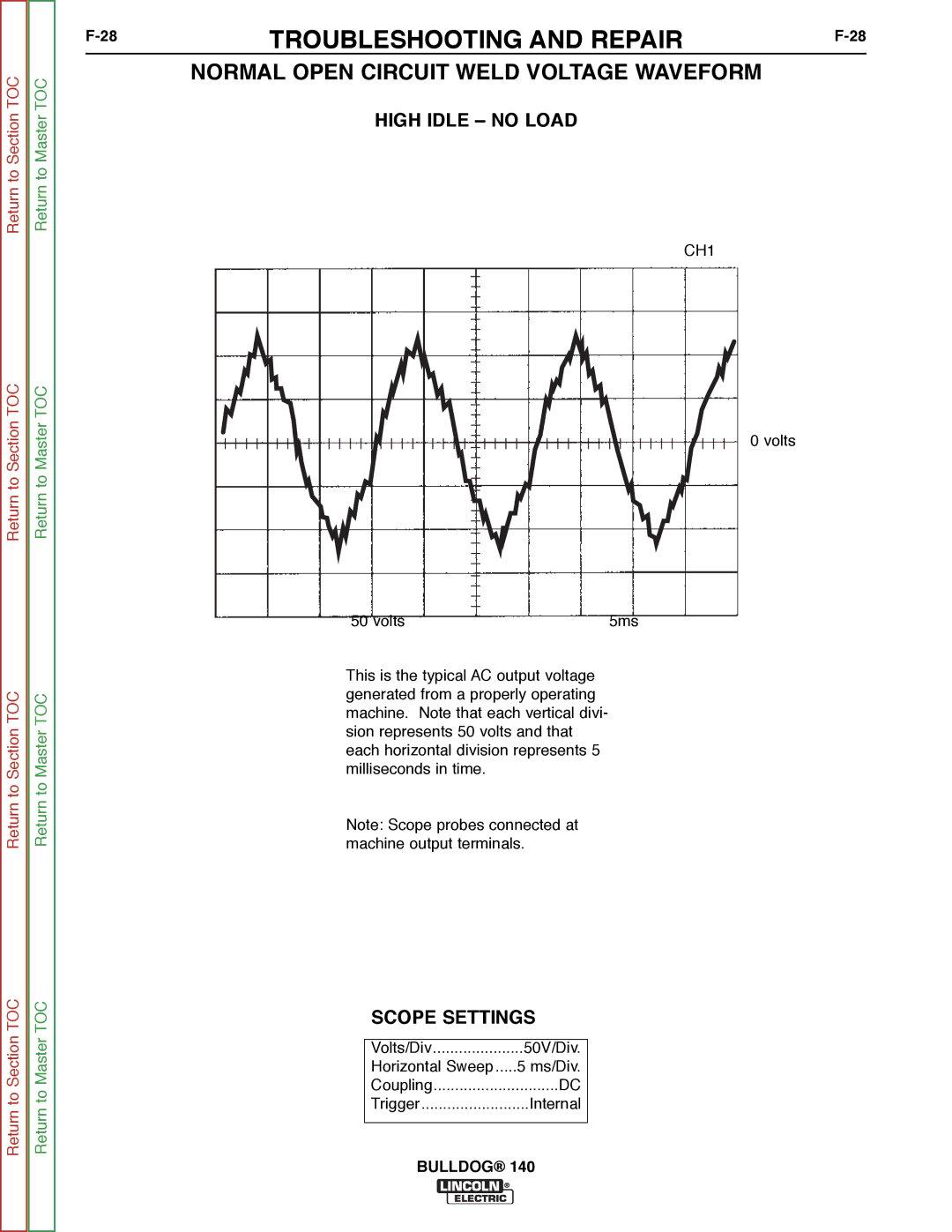
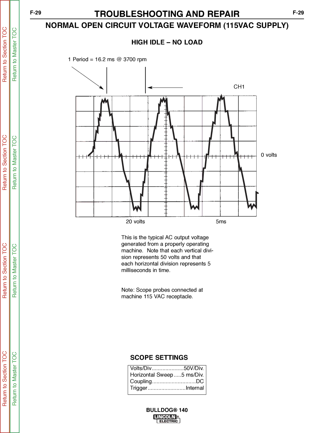
Contents Bulldog Safety California Proposition 65 WarningsElectric Shock can kill ARC Rays can burn Can be dangerousWelding and Cutting Sparks can cause fire or explosion Cylinder may explode if damagedIii Précautions DE Sûreté Sûreté Pour Soudage a L’ArcSafety Methods of Reducing Emissions Mains Supply Master Table of Contents for ALL Sections Table of Contents Installation Section Installation Technical Specifications Bulldog 140 K2708-1Storing Safety PrecautionsLocation and Ventilation Engine Exhaust can killTilting PRE-OPERATION Engine ServiceStacking OILElectrical Output CONNEC- Tions Welding Cable ConnectionsTable A.1 Recommended Welding Cable Size and Length Electrical Connections Auxiliary Power ReceptaclesCable Installation Plugs and HAND-HELD EquipmentPremises Wiring Circuit BreakersAtion. do not RUN These BulldogTable of Contents Operation Section Operation Limitations WELDER/GENERATOR ControlsOutput Panel Controls Engine Operation Gasoline Engine ControlsBefore Starting the Engine Starting the EngineGenerator Operation Table B.1 Generator Power Applications Welding Operation Control Function / OperationStick Welding Material Thickness Electrode Type Size SettingWelding Guidelines Learning To Stick WeldWhat Happens in the Arc? Correct Welding Position Side viewDo the following PracticeUse the following Butt JointsFillet Joints PenetrationVertical-Up Welding Vertical-Down WeldingWelding Sheet Metal How to Hardface the Sharp Edge Metal to Ground WearOverhead Welding Hardfacing To Reduce WearWelding Cast Iron Cast Iron Plate PreparationHigh-Speed Group AWS E6013 Low Hydrogen Group AWS E7018Out-of-Position Group AWS E6011 Bulldog Table of Contents Accessories Section Accessories OPTIONS/ACCESSORIESLincoln Electric Accessories Table of Contents Maintenance Section Maintenance Routine and Periodic Maintenance Engine MaintenanceLocation Engine Adjustments Return to Section TOC To Section TOCTable D.1 Engine Maintenance Parts Spark Plug ServiceOperational Clearance GENERATOR/WELDER Maintenance Screws BrushesFigure D.7. Major Component Locations Bulldog 1TABLE of CONTENTS-THEORY of Operation Section E-1 Theory of Operation ENGINE, EXCITATION, Rotor StatorRotor Field Feedback Auxiliary Power Figure E.3 Rotor Field Feedback and Auxiliary PowerAuxiliary Power Overcurrent Protection Weld Winding and Reactor1TABLE of Contents Troubleshooting and Repair F-1 Troubleshooting and Repair HOW to USE Troubleshooting GuidePC Board Troubleshooting Procedures Output Problems Electric Authorized Field Ser vice Facility Perform the Rotor Voltage TestProblems Symptoms Troubleshooting and Repair Perform Field Diode Test Engine Problems Troubleshooting and Repair Engine Throttle Adjustment Test Bulldog Rotor Voltage Test Test DescriptionMaterials Needed Procedure Rotor Voltage TestLead 200A Connection Ground Stud Field Diode Bridge Test Field Diode Bridge Test + ~Rotor Flashing Circuit Test Rotor Flashing Circuit Test Figure F.3 Brush Holder Leads 201- and 202B +Moving Parts can injure Bulldog Rotor Resistance Test Rotor Resistance Test Cable TIE Brushes Figure F.6 Brushes Retained with Cable TIEBulldog Engine Throttle Adjustment Test ROBIN/SUBARU Engine Strobe-tach Method Engine Throttle Adjustment TestROBIN/SUBARU Engine Frequency Counter MethodHigh Speed Stop Screw Scope Settings Normal Open Circuit Voltage Waveform 115VAC Supply High Idle no LoadTypical Weld Output Waveform Machine LoadedMachine Loaded to 125 Amps AT 23 VAC Brush Removal and Replacement Brush Removal and Replacement Cable TIE BrushesReturn to Section Return to Section TOC Bulldog Rheostat Removal and Replacement Rheostat Removal and Replacement Figure F.11 Rheostat RemovalCapacitor AND/OR Diode Bridge Removal and Replacement Removal and Replacement Procedure Capacitor Removal and ReplacementCapacitor AND/OR Diode Bridge Procedure Field Diode Bridge Removal and Replacement Figure F.13 Field Diode Bridge LocationBulldog STATOR/ROTOR Removal and Replacement InstructionsSTATOR/ROTOR Removal and Replacement GeneratorengineFigure F.15 Generator Components Troubleshooting and Repair Stator Removal Procedure Figure F.16 Output Lead Location TIE Wrap TerminalsThru Bolts Support NutsRotor Removal Procedure Reassembly ProcedureFigure F.19 Checking ROTOR-STATOR AIR GAP Engine Output Auxiliary Power Receptacle OUTPUT1Retest After Repair WELDER/GENERATOR OUTPUT1Bulldog Table of Contents Diagram Section Wiring Diagram Bulldog S28101