Epson 28-276 Adjusting the upper blade guides and blade support bearing, English

Page 19

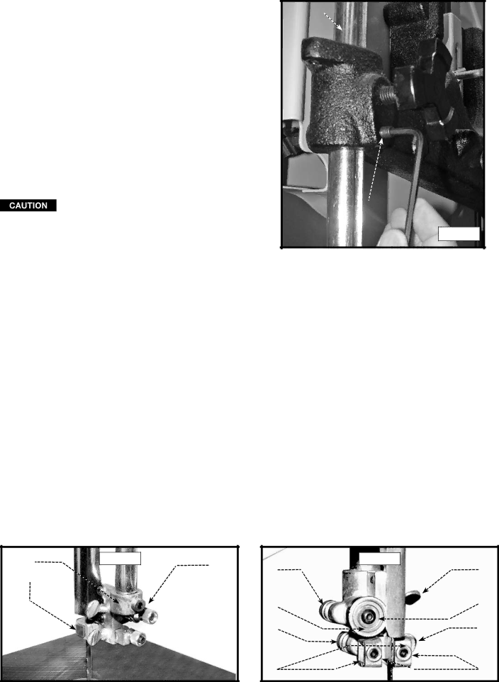
When removing the post, the friction pin (C) and compression ball (D) may come loose. To reinstall parts:

1.Remove adjustment set screw (E) Fig. 33B.

2.Install new guide post (F), making sure channel is oriented towards guide post lock knob (G) and tighten lock knob.

3.Place friction pin through hole in casting behind set screw (E) and then place compressing ball in same hole.

4.Thread adjustment set screw in place until tight.

5.Loosen guide post lock knob (G), the turn adjustment set screw (E) until desired force to move guide is attained.

Always tighten guide post lock knob prior to using the band saw

F

G

E

Fig. 33B

adjusting THE upper blade guides and blade support bearing

Adjust the upper blade guides and blade support bearings ONLY after the blade has the correct tension and is tracking properly. To adjust:

Disconnect the machine from the power source!

1.Confirm that the bottom blade guides and support bearings are not touching the blade.

2.Observe the upper blade guide assembly. The blade guides (A) Fig. 34 should be parallel to the blade. To adjust, loosen the screw (B) and rotate the complete guide assembly (C). When the blade guides are parallel with the blade, tighten the screw (B).

3.Adjust the guides (A) Fig. 35 so that the front edge of the guides are just behind the "gullets" of the saw teeth. You can move the complete guide block bracket in or out by loosening the thumb screw (C) and turning the knurled knob (D) Fig.

35.When the guides (A) are set properly, tighten the thumb screw (C).

4.Two set screws (B) Fig. 35 hold the upper blade guides (A) in place. Loosen the set screws (B) to move the guides (A). Place them as close as possible to the side of the blade. (Do not pinch the blade). Tighten the screws (B).

5.The upper blade support bearing (E) Fig. 35 prevents damage to the set in the saw teeth by keeping the blade held forward. Set the support bearing (E) 1/64" behind the blade. Loosen the thumb screw (F) and turn the knurled knob (G) to move the support bearing (E) in or out.

6.Adjust the blade support bearing (E) so that the back edge of the blade overlaps the outside diameter of the ball bearing by about 1/16". The bearing (E) is set on an eccentric. To change the position, remove the screw (H) and bearing (E) Fig.

35.Loosen the thumb screw (F), and back out the knurled knob from the set screw. Remove the hex shaft from the hole, and rotate it to move the eccentric for the bearing.

7.When the blade guide wears so that it cannot be adjusted close to the blade, loosen the screw (B) Fig. 35 and reverse the blade guides (A) Fig. 35.

C A

Fig. 34

B


Fig. 35

G

F


E

H


D

C


A

B


19 - English


Image 19
Contents Contractors Saw Important Safety Instructions Table of ContentsSafety Guidelines Definitions General SAFETY RULES SAVE THESE Instructions ADDITIONAL SPECIFIC SAFETY RULESMOTOR SPECIFICATIONS Power ConnectionsGrounding Instructions Fig. C EXTENSION CORDSFunctional Description Carton ContentsModel 28-206 Enclosed Stand Parts Model 28-276 Open Stand Parts Model 28-206 Enclosed Stand Assembly AssemblyAssembly Tools Required Assembly Time EstimatePage Model 28-276 Open Stand Assembly Page Attaching the Belt to the SAW and Motor Pulley Attaching the SAW to the StandAttaching the Pulley Guards Table Insert CONNECTING MOTOR CORD TO SWITCH ASSEMBLYDisconnect the machine from the power source Attaching Blade to the SAWStarting and stopping the saw Locking the switch in the off positionTilting the table Adjusting blade tension Adjusting the table stopAdjusting Tightness of ANTI-DROP Screw Vertical Adjustment of the upper Blade guide assemblyTracking the blade English Adjusting the upper blade guides and blade support bearingDust Port Adjusting lower blade guides and blade support bearingChanging Blade Speed for Model 28-206 only CUTTING CURVES Troubleshooting GuideProbable Cause Remedy Probable Cause Remedy Pointer out of adjustmentProbable Cause RemedyBand SAW Blades Service MaintenanceWarranty AccessoriesService and Repairs Mesures DE Sécurité Définitions LES Instructions Importantes DE SureteRègles DE Sécurité Générales Conserver CES Directives Règles Spécifiques Additionnelles De SûretéFrench Raccordements ÉlectriquesSpécifications DU Moteur Instructions DE Mise À LA TerreFonctionnement Monophasé À 240 Volts Cordon DE RallongeDésemballage ET Nettoyage Description FonctionnelleContenus DE Boite AVANT-PROPOSPièces DU Socle Fermé DU Modèle Pièces DU Socle Ouvert DU Modèle Assemblage DU Socle Fermé DU Modèle AssemblageOutils Nécessaires Pour L’ASSEMBLAGE Durée Estimée Pour L’ASSEMBLAGEFrench Assemblage DU Socle Ouvert DU Modèle French Assemblage DES Protecteurs DE Poulie Assemblage DE LA Scie SUR LE SocleInsert DE Table Connexion DU Cordon Moteur À L’ENSEMBLE DE L’INTERRUPTEURAssemblage DE LA Table SUR LA Scie Assemblage DE LA Lame SUR LA ScieInclinaison DE LA Table FonctionnementDémarrage ET Arrêt DE Scie Verrouiller L’INTERRUPTEUR EN Position D’ARRÊTRéglage DE LA Tension DE Lame Réglage DE LA Butée DE LA TableNe jamais aligner la lame lorsque l’appareil fonctionne Alignement DE LA LameRéglage DU Serrage DE LA VIS DE Prévention DE Tombée Débrancher l’appareil de la source d’alimentation Coupe DE Courbes Goulotte À PoussièreProblème LES Lames Cassent Cause probable Problème LA Scie NE Démarre PAS Cause probable SolutionGuide DE Dépannage Problème LA Scie À Ruban Vibre Beaucoup Cause probableProblème LA Lame NE S’ALIGNE PAS Cause probable Lames DE Scie À Lame RubanEntretien Garantie AccessoiriesPautas DE SEGURIDAD/DEFINICIONES Instrucciones DE Seguridad ImportantesNinguna aplicación de otra manera que para que se diseñó Normas Generales DE Seguridad Normas Específicas Adicionales DE Seguridad Guarde Estas InstruccionesESPECIFICACIONES DEL MOTOR Conexiones a LA Fuente DE AlimentaciónFig. D1 Cordones DE ExtensiónContenido DE Carton Descripción FuncionalPrologo Base Tornillo de cabeza troncocónica M5 x 0.8 x 10 mm Lado Piezas Cerradas DEL Soporte DEL ModeloPiezas Abiertas DEL Soporte DEL Modelo Montaje DE LA Base DE Soporte Cerrada Modelo EnsamblajeHerramientas DE Ensamblaje Requeridas Estimación DEL Tiempo DE EnsamblajeNota Apriete libremente el hardware para el ajuste adicional DA B Montaje DE LA Base DE Soporte Abierta ModeloPage Conectar LA Agujeros DEL Protector DE LA Polea Sujeción DE LA Sierra a LA Base DE SoporteMontaje DE LA Pieza DE Insercion DE Mesa Cuerda DEL Motor QUE Conecta a LA Asamblea DE InterruptorSujeción DE LA Mesa a LA Sierra Sujeción DE LA Hoja a LA SierraInclinación de la tabla OperaciónArrancando Y Deteniendo LA Sierra Bloqueando EL Interruptor EN LA Posicion DE ApagadoAjuste de la tensión de la lámina Ajuste de la parada de la tablaAjuste Vertical del montaje superior de la guía de la lámina Seguir la láminaReajustar Piezas CON Bloqueo CON Accesorios DE Altura Ajuste DE LA Tensión DEL Tornillo CON BloqueoDesconecte la maquina de la fuente de energia Puerto del polvo Utilizar LA MaquinaRemedio Guia Localizacion DE FallasCorte DE Curvas Causa probableRemedios Hojas DE Sierra DE Cinta MantenimientoMantenga LA Máquina Limpia Mantenimiento Y Reparaciones ServicioFalla EN EL Encendido Lubricación Y Protección Contra ÓxidoIdentificación Delproducto AccesoriosExcepciones Para Otras Localidades GarantiaGarantía limitada de dos años para productos nuevos