Conair UGR003/0800 manual Adjusting Traverse Movement

Page 45

When changing to a new mold, the traverse (horizontal) move- ment of the arm may need adjusted. To adjust the traverse movement:

1

Press the Manual button on the control to


place the robot in manual mode.


2

Move the main arm to the Home position


using the control buttons.


3

Lower the main arm into the open mold and


see if the grip is centered over the mold. If it is not, you


need to adjust the traverse movement.


4

Retract the main arm to the Home position.


This locks the main arm vertically.


5

Turn off the air pressure to the robot and


drain the air.


EQUIPMENT DAMAGE


Always turn off and drain air from the robot


before adjusting the traverse movement.


Damage can occur to equipment!
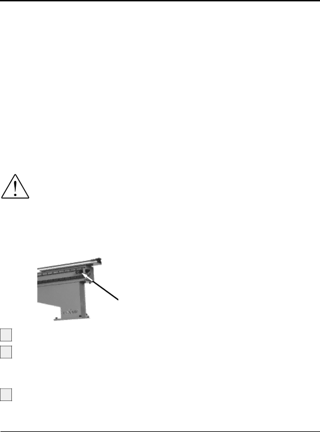


6

Adjust the shock absorber until it is set


completely against the arm and the arm is centered verti-


cally over the sprue. Lock the shock absorber by tighten-


ing the locknut.

ADJUSTING

TRAVERSE

MOVEMENT

Shock absorber

7

8

Connect the air line and turn air on.

Using the manual control buttons, extend the

main arm and grip. Check alignment with the mold and sprue. If alignment is incorrect, repeat steps 4 - 7 until alignment is correct.

9

Press the Mon I/O button on the control.

The Home input (LSH) should be ON (O). If it is OFF

(X)move the Home actuator on the back of the traverse beam until the Home input registers ON.

UGR003/0900

UCR-150L Robot

OPERATION 4-15

Image 45
Contents UCR-150L Robot Date Document Number Introduction Table of ContentsMaintenance Introduction Purpose User Guide HOW the User Guide is OrganizedYour Responsibility AS a User Read this SO no ONE Gets Hurt Page Description What is ROBOT?Typical Applications Robot Works HOWWrist flip cylinder Robot FeaturesFront view Side view SpecificationsOptional Equipment Extended strip strokeEnd-of-arm tooling Installation Remove all packing material Unpacking the BoxesInstallation Preparing for Installation Mounting pattern for the UCR-150L Robot Preparing the PlatenPositioning the Robot Connecting the RobotCheck to see what the power output is from Connect the SPI connector cable intoPlug the hand-held control into the control Tighten the adjustment screws on the block Setting Gripper PositionOpen the mold Hold the main arm and loosen the arm height Set the gripper height to the sprueSetting Strip Positions Adjusting Sprue Verification Switch Connecting AIR PressureAdjusting the Speed Verifying motion controls permissives Verifying Electrical InterfaceMold Full Open Verifying the InputsManual Testing Automatic Testing Press the Stop buttonPress the Auto/Recycle button Page Operation Before Starting Hand Control FeaturesStarting the Robot Stopping the RobotEmergency Stopping Grips Viewing InformationOperating Manually Starting Automatic Operation Press the Program button Choosing the MoldUse the Up and Down arrows Press the Enter buttonProgramming Motion Sequence Press Stop buttonPress Program button Continue to move through the motion Use the Forward arrowPress the Function button Programming HOME, Grip Vacuum PositionsChoose the function and settings you want Use the right arrow to choose the settingPress the Stop button to continue Inputs Monitoring INPUT/OUTPUTEnter the new timer value Setting Timer ValuesPress the Time button Press the Forward buttonTimer Setting Description LCD Displays Choosing Timer SettingsAdjusting Traverse Movement Open the safety door and verify that there is Answering AN AlarmRestarting Automatic Operation Use the Motion Control buttonsMaintenance Maintenance Features Maintenance Daily Preventative Maintenance ScheduleMonthly Checking Electrical Connections Be sure the main power is disconnectedTroubleshooting Identifying Cause of a Problem Before BeginningFEW Words of Caution Error Display Area of problem Robot Does not Cycle Symptom Possible cause SolutionMold is Not Working Properly Safety interlock is on. Check the output and wiringARM is Not Working Properly Strip Motion Is not Working Horizontal Motion There is noGripper does not work Gripper Does not WorkThere is no vac Air pressure is incor Uum Rect WE’RE Here to Help HOW to Contact Customer Service Before YOUFrom outside the United States, call Appendix GUARANTEE/WARRANTY Electrical Diagrams Solenoid and Limit Switch Wiring Relay and IMM Interface Solenoid Valves Page PARTS/DIAGRAMS PARTS/LISTS Ref. Part No Description Traverse Cylinder IMR004/0800 UCR-150L Robot PARTS/DIAGRAMS P/D-5 Valve IMR004/0800 UCR-150L Robot PARTS/DIAGRAMS P/D-7 Valve Parts JSU6 Slide Base YSA10DC-50B Strip Cylinder U3-MA0-LS Main Arm Description Quantity Main Arm Slide Unit LM20UU Main Cylinder IMR004/0800 UCR-150L Robot PARTS/DIAGRAMS P/D-19 Wrist Flip TANSI6P Wrist Flip Cylinder IMR004/0800 UCR-150L Robot PARTS/DIAGRAMS P/D-23 Gripper Assembly D12 D9191 Assembly, Gripper, with LS-4 Gripper GXL-8F Controller HW-CB116B