Sterling Plumbing 882.00254.00 Installing ArmorBlocks, Using seal block to pierce cable

Page 22

Installing ArmorBlocks

The ArmorBlock cable base should already be attached to the mounting plate, aligned so it is perpendicular to the flat cables. If not, reinstall it with its proper alignment.

To install the flat cables in the ArmorBlock cable base:

1.Lay the flat cable into the ArmorBlock cable base, grey data cable on the bottom and the black power cable on the top, making sure that the keyed edge is properly seated toward the top.

Caution! EXERCISE CARE when handling the seal block. Cable contacts are SHARP!

Only ONE attempt to pierce the cable is allowed for proper contact.

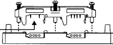
Figure 6: Using seal block to pierce cable

2.Align the seal block so the L-shaped tabs are towards the top, and the arrows are matched on the bottom of the cable base and seal block. Make sure that the arrows and the four captive screws on the seal block are properly aligned. Gently press it into place.

Make sure that you align the seal block properly when you attach it to the base. Doing so maintains the integrity of the sealed base.

Note: You can only pierce the cable once. Once pierced, the seal block must not be removed. This insures that the inner conductors are not exposed to the elements.

7/50D Plus or 7/50D Controller

Chapter 3: Installation

21

Image 22
Contents SCC 7-Pump 50D & D Plus-Station Controllers Parts and Service Department Shipping Information Table of Contents Maintenance Controller Safety Tags How to Use This Manual SafetySafety Symbols Used in this Manual Wear Safety Glasses and Work Gloves Responsibility General ResponsibilityReporting a Safety Defect Maintenance ResponsibilityOperator Responsibility Models Covered in This Manual Functional DescriptionGeneral Description Electrical Features Standard FeaturesMechanical Features Controller FeaturesSafety Circuit Standards Optional FeaturesSafety Devices and Interlocks Fail Safe OperationSafety Device Lock-Outs Uncrating InstallationSystem Installation Overview Mounting the Control PanelRunning KwikLink Cables Making Control Panel Power Drop Wiring ConnectionsElectrical Connections About KwikLink Flat CablesInstalling KwikLink Cable Setting Up Mounting Plates Setting Up and Installing Mounting PlatesInstalling Assembled Mounting Plates Terminating Cable Runs Discard the standard resistor cap to eliminate confusionInstalling Inside KwikLink Connectors with Blank Caps Proper Termination ConnectionsAddressing Armorblocks Addressing and Installing ArmorBlocksSetting Armorblock Addresses ArmorBlock Address RangesInstalling ArmorBlocks Using seal block to pierce cableSecuring the Seal Block to the Cable Base Installing KwikLink Connectors Connecting the Controller to the Network Connecting the Remote Interface to the Main ControllerProper Controller and Remote Interface Connections Connecting the Power Supply Enclosure to the Network Proper Power Supply Enclosure Connections Connecting Vacuum Receivers to the Network 50D 4-Connector ArmorBlock ConnectionsPlus Connections Connecting Vacuum Pumps and Filter Chambers to the Network Connecting Vacuum PumpsProper Vacuum Pump Connections Connecting Filter Chambers Proper Filter Chamber ConnectionsConnecting Central Alarms to the Network Proper Central Alarm ConnectionsAlarm Horn C-O1 Setup Basic Menu Flow for SetupSetting Up the System Setting the Number of Stations and the Number of Pumps50D Plus Screen shown Checking Addressing and Wiring for System Components Page Page Setting Up Alarm Silences Setting Up Pump Staging Setting Up Touch Switch DelaySetting Up Stations Setting Up a Single Station50D Plus shown Copying Settings from One Station to Others To copy the selected station’s settings to one other station Setting Up Pumps Setting Up a Single PumpPage Copying Settings from One Pump to Others To copy the selected pump’s settings to one other pumpTo copy the current pump’s settings to all other pumps Finishing Setup Setting Up Passwords Page Initial Startup Overview OperationStarting and Stopping the System Basic Tasks Reviewing Station StatusColor Label Description Reviewing Pump Status Color Label Description Logging On and Logging Off Enabling and Disabling Stations and Pumps Reviewing and Adjusting Basic Station Settings Reaching and Reading the Station Operator ScreensAdjusting Convey Time and Dump Delay Navigating among the Station Operator ScreensActivating and Stopping Priority Convey for a Station Changing the Mixture for a Remote Proportioning ValveAdvanced Tasks Changing the Line with Material ProofingReviewing and Resetting a Pump Hour Meter Transferring Stations to a Standby Pump Page Page Alarms Reviewing AlarmsClearing the Alarm Log Touch ContinueSilencing Alarms Corrective Maintenance MaintenancePreventative Maintenance Network Scanner Module ConsiderationsOptions for Station Setup Configurable SettingsMemory Module Considerations 50D Plus or 7/50D Controller Configurable Settings Blow Back Options Only available on 7/50D Plus systems Only available on 7/50D Plus systems 50D Plus or 7/50D Controller Configurable Settings Options for Pump Setup 50D Plus or 7/50D Controller Configurable Settings Troubleshooting General TroubleshootingStation Alarms Alarm message Possible causePump Alarms System Alarms Appendix WarrantyOptional Components Drawings and Diagrams Pump 50 station Controller with ??? DisplayTypical System Installation Layout 50D Plus or 7/50D Controller Appendix AC Voltage Spare Parts ListReturned Material Policy DC VoltageController Safety Tags Safety Tag InformationWarranty Returns Controller Identification Serial Number TagParts Department Service DepartmentTechnical Assistance Contact Information Sales Department