User Guide
United States Government Legends
Contents
Rapid Configuration
Power-Up
Normal operation Fast Ethernet Status Indicators
Parameter Entry Quick Key Functions Menu Index
Display Broadcast Throttling Attributes
Remove a Static Address from FDB Display STP Enable Status
Fast Ethernet Port Attributes and Statistics
Display Bridge STP Attributes
Display Current LEC Configuration
Managing ATM Resources
Enable/Disable Event Messages 10-14
Display Snmp Configuration
Update NMS IP Address
Display Software Version 10-2
12 ATM, LAN EMULATION, and Virtual Lans
12-7
12-15
12-14
Bridge Frame Forwarding Logic
13-5
Fast Ethernet Card Specifications Physical C-1
Glossary
Guide
About this Guide
If you are looking for information about Turn to
Conventions
Conventions
Tables 1 and 2 list conventions used throughout this guide
7600 Card Documentation and Related Manuals
7600 Card Documentation Road Map
If you want to Read
Card
Overview of the 7600 Card
About
Card
Front Panel of the 7600 Card with full configuration
3Physical module with SC connector for fiber ports
Capabilities
4CHAPTER 1 Overview of the 7600 Card
Typical Applications of the 7600 Card
5Fast Ethernet backbone
Server farm
Starting UP
Installation and POWER-UP
Safety Precautions
Mesures de sécurité
Vorsichtsmaßnahm en
Removing
Installing
Card Modules
Connection to a workstation or other DTE, using a normal
Connecting to
Network Devices
Local Management
Connecting to a
Terminal
States
System Power green Fail red Active orange
Card System
How they are indicated on the LED display
When the 7600 Card is powered-up, it automatically begins
Power-Up
Power-up phase and initiates the Power-On Self-Test
Mode Meaning and User Action
4Fast Ethernet Port LEDs
LED Color Meaning
Configuration
Fast Setup
Rapid
Full Setup Mode
Setup
Setup Modes
CELLplex
Setup Mode Selection
Switch Setup Mode
Setting Special Parameters
Setup Section Description
1Integrated Fast Setup Procedure Sections
2Setup Procedure Navigation Aids
Sections
Operation
Integrated Fast Setup is initiated from the LMA Main Menu
Select the menu item 9 FST Fast Setup
CELLplex 7000. The CELLplex Main Menu appears as follows
Example Dialog The following dialog appears on the screen
Network Prefix Section
Lecs Address Section
LE Parameters Section
UNI/NNI Parameters Section
LE Client Configuration Section
Virtual Network Configuration Section
Admin VN Management Configuration Section
Confirmation Dialog Section
Port Context
Setup to perform a rapid configuration of the 7600 Card
Multi-context Fast
Contex
4Setup Procedure Navigation Aids
Type To go to
Admin Main Menu appears as in the following example
Elan Configuration Section
Management Configuration Section
System Mode Configuration Section
New configuration is displayed for this context
Card Management Tasks
Management
Local Management Basics
Menu Hierarchy
Main menu
Example
Keying in this submenu’s 4 option gives you the prompt
Entry of the stp submenu’s 3 option produces the prompt
Finally, entering 1 finalizes the prompt as
2Menu Navigation Functions
3Editing Aids
Menu hierarchy
Menu Index
System Management Menu
Bridge Menu
ATM Menu
LAN Emulation Menu
Virtual LAN Menu
Network Management Menu
Display Current
Configuring Virtual Lans
Configuring Bridges
Bridge
Ethernet Port to
2Bridge Configuration Parameters
Attach Fast
Enter 6 Following is displayed
Fast Ethernet port #3 is attached to bridge #1
Attach Internal
ATM Port to Bridge
Internal ATM port is attached to bridge #0
Managing Ethernet Bridges
Management Tasks
Managing Fast Ethernet Ports
Managing the Bridge Forwarding Database
Statistics
Fast Ethernet Port
Attributes
Managing the Spanning Tree Protocol Bridge-wide
4Ethernet Port Statistics
3Fast Ethernet Port Characteristics
2Ethernet Port Attributes
Name Description
Following information for Port #1 is displayed
1Fast Ethernet Port Attributes and Statistics Display
Display Broadcast
Disable a Fast
Ethernet Port
Throttling
Threshold
Enable/Disable
Broadcast Throttling
9Task Actions
10Task Actions for Fx Port Type
Example 2 for Fx port type
Example 1 for Tx port type
Fast Ethernet Tx port #1 is set to half duplex
11Task Actions for Tx Port Type
13Bridge Attributes and Statistics
3Bridge Attributes and Statistics Display
Time
Update
Bridge-aging
Bridge-port
16Bridge-port Attributes and Statistics
4Bridge Attributes and Statistics Display
Database
Display All Entries
Forwarding
17 Task Actions
5Forwarding Database Display
Learning Station Addresses on
Display Learned
Entries
19 Task Actions
Forwarding Database see Static Addresses on
Display Static
21Task Actions
22Static Table Fields
23Hexadecimal Codes for Displaying Multiple Bridge Ports
Static Addresses Allowed-to Binary Table
Bridge Ports Hex Value Bridge Ports Hex Value
7Static Table Display
Address
Block a Static
Static Forwarding Database of bridge #0, the MAC address
Ports #4
Remove a Static
Address from FDB
Database see Static Addresses on
About the STP enable status see Disabling the STP on
Display STP Enable
Disable STP on
Status
30Bridge STP Attributes
STP attributes for bridge #0 is displayed as follows
9Bridge STP Attributes Display
Bridge-wide STP
Parameters
Bridge-forward-delay for bridge #0 is set to 1500 secs
Update Bridge-forward Delay
Example Enter
STP Attributes
36Bridge-port STP Attributes
Attributes of port #1 of bridge #0 are displayed as follows
10Bridge-port STP Attributes Display
Bridge-path-cost
Bridge-path-cost for port #1 of bridge #0 is set to
Manage ATM port
Update ATM parameters
Managing ATM Resources
Manage Bridge ATM addresses
Enter 4
Display ATM Port Attributes Statistics
2ATM Port Attributes and Statistics
4ATM Address Fields
Following sample ATM statistics report is displayed
Field Description
Following is a sample ATM address display
2ATM Address Display
More information about Traffic Management in the 7600 Card
Display TM
5Task Actions
Enable TM
Toggles TM operation on and off
TM remote Client Database is displayed as follows
Characteristic Range Default Meaning
9Task Actions
Add TM Client
Information see Display TM Clients on
Up to enable the ATM port or down to disable the ATM port
Enable/Disable ATM
Port Admin Status
Selected version is saved in flash
Context #0 Event ATM port Link Up
Display statistics
Manage configuration parameters
Managing LAN Emulation Clients
Manage operational parameters
Manage data-frame parameters
Update Unknown Unicast-flood- Mode
Display LEC
Transmission over an Elan on
Enter 5 1
Lecs Information Description
4LEC Configuration and Status Information
LES Information Description
2LEC Configuration and Status Display
BUS Information Description
See LAN Emulation Overview on
Update Lecs
Enter the bridge number and ATM address or ! to invalidate
Elan name for the LEC of bridge #0 is entered
LES address for the LEC of bridge #0 is entered
Enable Lecs
Address via Ilmi
LAN Emulation Overview on
10LEC Operational Parameters
Operational
10. For more information see LEC Parameters on
LEC Parameter Description
VCC-timeout-period, aging-time, forward-delay-time
Update LEC
Update the LEC operational parameters control-timeout
Control-timeout parameter in seconds
Enter 533 0
Enter 535 0
18Task Actions
19Task Actions
Connections on
Control-frame
Refer to -21. For more information see Emulated LAN
20Task Actions
Enter 54
16CHAPTER 8 Managing LAN Emulation Clients
Mode
Update Unknown
Unicast-flood
Unknown Unicast Frames on
LE flood mode for Bridge #0 is now NotFlood
Setting Network Parameters
Display Snmp Configuration Update NMS IP Address
2IP Configuration Information
Display Current IP
Default Gateway for the specified bridge
Update Default
IP Address for bridge #0 is updated to
Default Gateway for bridge #0 is updated to
Mask
Update Subnet
Display Snmp
Update NMS IP
Traps
Managing System Functions
Version
Resetting system
Display Software
Manage event messages
Download
Download Status
Software from Network
Software from
Erase Software
From Flash
Local
Display Hardware Configuration
Current system configuration mode
Set System
After the next reset
Forward Mode
Set Store-and
For descriptions of the timeout parameters
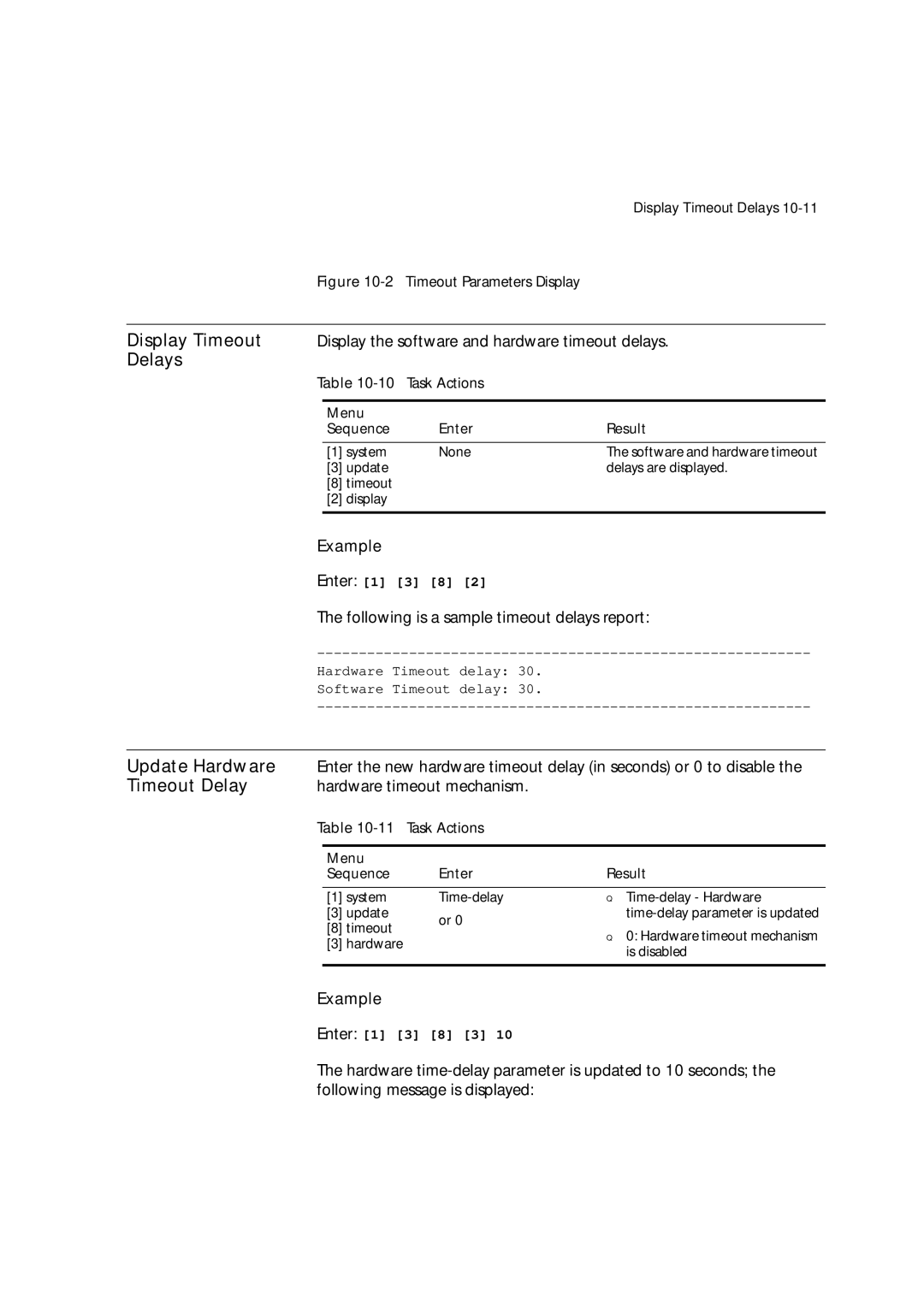
Display Timeout
9Timeout Parameters
Following is a sample timeout parameters report
CPI
Update Hardware
Delays
Timeout Delay
Update Software
Software timeout mechanism
Updated
Password
Write-access
Admin-access
Event Messages
System hardware is reset and device is rebooted
Enter 1
III 7600 Card Capabilities
Overview
Ethernet
Fast Ethernet
10/100 Mbps transmission speed
Full or Half Duplex Mode
Auto-negotiation
2Cable Support by Transceiver Type
10 or 100 Mbps Speed
Transceiver type Cable type Number Pairs fibers
Fast Ethernet Ports
11-6CHAPTER 11 Ethernet Lans and Bridges in the 7600 Card
Transparent Bridges
Address of a bridge port, called Self
Spanning Tree
Protocol
Can be defined as follows
Spanning Tree Protocol
Designated Bridge on a LAN Spanning Tree port selection
3Port-independent Bridge Parameters
Parameters in -4 are set for individual bridge ports
4Port-dependent bridge parameters
11-12CHAPTER 11 Ethernet Lans and Bridges in the 7600 Card
Virtual Lans
ATM Overview
ATM Basics
Virtual Channels
Interim Local
Interface Ilmi
LAN Emulation
BUS
LAN Emulation
Emulated LAN
Connections
Control VCCs
Illustrates the VCCs active among LAN Emulation Components
3LEC Configuration and Status Information
Elan Name
Both local and remote destination LANs in the ATM network
Bridges
Bridge acts like a standard transparent bridge
2Bridges in the 7600 Card
12-12CHAPTER 12 ATM, LAN EMULATION, and Virtual Lans
Bridges in the 7600 Card
Entry obtained by Topology flag Aged by
Mode Bridge action
Unknown unicast flooding mode
5Unknown Unicast Flooding Mode
Data Transmission over an Elan
Flush protocol
Parameter Description Minimum Default Maximum
LEC Parameters
Be set by management
Virtual LANs
12-18CHAPTER 12 ATM, LAN EMULATION, and Virtual Lans
Virtual LANs in the 7600 Card
12-20CHAPTER 12 ATM, LAN EMULATION, and Virtual Lans
Workgroups
Each vLAN communicates with its server
6Logical and Physical View of a Network With vLANs
Topics are discussed
ATM Network
How Traffic Management is implemented within the 7600 Card
1Example of a source to destination ABR control loop
This congestion information
Traffic
Management Concepts
Generate backward RM-cells
Traffic
Functions
7600 Card checks connected devices for Traffic Management
Configuration
ATM technology without having cell loss due to congestion
Found in the connected device
13-6CHAPTER 13 Traffic Management in the ATM Network
As shown. The traffic management is performed as follows
2Traffic Management control steps
Device Management
Protocols
In-Band
Out-of-Band
Local Management
27600 Card Administration Console
Snmp Agents
Bridge MIB AToM MIB LE Client MIB
Management Information Bases MIBs
Interface Evolution MIB Ncdchass MIB private
Security
5Local Management Protocol Access
Tuning
Store-and-Forward Mode
Card for extended periods of time. This usually occurs when
Timeout Tuning
Cut-Through Mode
Terminating them as erred frames
Console Passwords
On-Line Technical
Services
Service
3Com Bulletin Board
Press Enter to see the Ask3Com main menu
Table A-2Automated Fax Service
Country Fax Number
Table A-3Telephone Support
Country Telephone Number
Table A-5Obtaining an RMA Number
Table A-6Local Access Numbers
Table A-4Network Supplier Support
Country Telephone Number Fax Number
Troubleshooting
Cleaning Dirty Fiber Optic Cables
Related Diagnostic Procedures
Physical
Fast Ethernet Card C Specifications
Fast Ethernet Switching
Interfaces
Indicators
Environmental
Standards Compliance
Glossary
Equipment DCE
Interface NNI
Call
Out-of-band
Point-to-point call
Protocol
Interface UNI
Index
Numbers
BUS
Elan
LEC ID
NNI
STP
VCC
Index