SuperStack Switch User Guide
3Com Corporation 5400 Bayfront Plaza Santa Clara, California
Contents
Installation and Setup
Virtual Lans Vlans
Forwarding Database FDB
Quality of Service QOS
Using the WEB Interface
Technical Specifications Troubleshooting
Page
About this Guide
Ethernet concepts Ethernet switching and bridging concepts
Icon Description
Conventions
Convention Description
Screen displays
Documentation
Related
Year
Compliance
About this Guide
Switch
Switch 9100 Overview
Features
About
Simple Network Management Protocol Snmp
Virtual LANs VLANs
For information on load sharing, refer to Chapter
Quality of Service QoS
Configuration
Network
Example
Key
Switch 9100 used in a backbone configuration
Ports
Front panel has the following features
View
LEDs
Describes the LED behavior on the Switch
Standard Media Type Mhz/Km Rating Maximum Distance
Color Indicates 1000BASE-SX Port Status LEDs
Unit Status LED
Switch 9100 Rear shows the Switch 9100 rear view
Color Indicates 100/1000BASE-TX Port Status LEDs
Reset Button
Power Sockets
Serial Number
MAC Address
Public
Location
Installation and Setup
Determining
Rack Mounting
Installing
Tabletop
Installing the Switch 9100
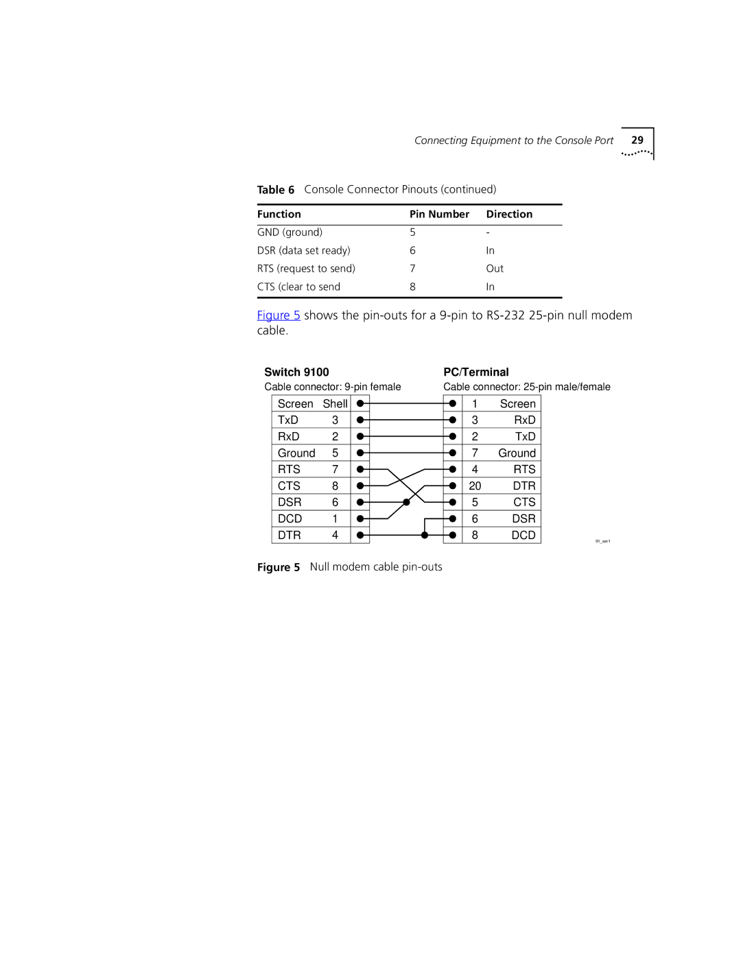
Function Pin Number Direction
Connecting Equipment to the Console Port
Switch
Flashes until the switch has successfully passed the Post
Installation
Login admin
Default Vlan named default
Logging on for
First Time
Installation and Setup
Accessing the Switch
Accessing the Switch
Be a range of numbers, for example
You could enter the following shortcut
Config vlan name ipaddress ipaddress
Symbol Description
Config snmp community readonly readwrite string
Reboot date time cancel
Line-Editing Keys
Create account admin user username encrypted password
Command Description
Disable cli-config-logging
Disable bootp vlan name all
Disable clipaging
Disable idletimeout
Unconfig switch all
Configuring Management Access
Show banner
3C177052
3C1770519#
Changing the Default Password
Account Name Access Level
Show accounts
Create account admin user username encrypted
Viewing Accounts
Using Access
Methods Managing Switch
Profiles
Deleting an Account
Config access-profile accessprofile
To view the contents of an access profile, type
Access Profile Example
To view the Telnet configuration, type
Using Telnet
Connecting to Another Host Using Telnet
Using a Bootp Server
Manually Configuring the IP Settings
Config iproute add default ipaddress metric
Config vlan name ipaddress ipaddress subnetmask
For example
Your changes take effect immediately
Clear session sessionnumber
Terminate the session by using the following command
Show session
Using the Web
Commands
On the switch
IP Host
Accessing Switch
Using Snmp
Agents
Supported MIBs
Enable Snmp traps
Enable Snmp access
Command
Options for the ping command are described in Table
Ping command syntax is
Checking Basic
Connectivity
Configuring Switch Port Speed Duplex Setting
Switch 9100 Ports
Enabling
Disabling
Enable ports portlist
Enable learning ports portlist
Enable sharing masterport
Config ports portlist qosprofile
Disable ports portlist
Disable learning ports portlist
Disable sharing masterport
Show ports portlist txerrors
Accessing the Switch
Enable sharing 4 grouping
Port-Mirroring
Configuration
Verifying the Load
Sharing
Disable mirroring
Commands
Example
Show mirroring
Accessing the Switch
VLANs provide extra security
VLANs help to control traffic
Igmp Snooping
Igmp Overview
VLANs ease the change and movement of devices
Forward-mcrouter-only Forward-mcrouter-only is specified,
Enable igmp vlan name
Enable igmp snooping
Port-Based VLANs
Types of VLANs
Marketing Finance Sales
Spanning Switches with Port-Based VLANs
Switch
AccountingEngineering
Assigning a Vlan Tag
Uses of Tagged VLANs
Tagged Ports
Shows a logical diagram of the same network
Mixing Port-Based and Tagged VLANs
NetBIOS DECNet IPX8022
Following protocol filters are predefined on the switch
Predefined Protocol Filters
AppleTalk
Create protocol protocolname
Config protocol protocolname add protocoltype Hexvalue
Defining Protocol Filters
Packets Over Protocol
Vlan Names
Deleting a Protocol Filter
On the Switch
Configuring VLANs
6 to it
Show vlan name
Displaying Vlan Settings
To display Vlan settings, use the following command
Deleting VLANs
Virtual Lans Vlans
Forwarding Database FDB
Associating a QoS Profile with an FDB Entry
Disable learning ports
Config fdb agingtime number
Entries
Following example adds a permanent entry to the FDB
Show fdb macaddress vlan name portlist Permanent
To display FDB entries, use the command
Displaying FDB Entries
Name Clear fdb macaddress vlan name portlist
Removing FDB
Delete Fdbentry macaddress vlan
Forwarding Database FDB
Overview
Spanning Tree Protocol STP
Spanning Tree
Protocol
Network with an illegal topology
Traffic flowing through Bridge B
Initialization
Stabilization
Reconfiguration
Domains
STPD2 contains VLANs Manufacturing and Engineering
Stpd
Marketing & Sales Marketing, Sales & Engineering
Config stpd stpdname add vlan name
Configuring STP on the Switch
Enable stpd stpdname
Create stpd stpdname
Enable stpd port portlist
Shows the commands used to configure STP
Through 3, and port
Settings
Displaying STP
Listed in Table
Resetting STP
Spanning Tree Protocol STP
Building Blocks
Quality of Service QOS
Quality of Service
QoS Profiles
Profile Name Priority Minimum Bandwidth Maximum Bandwidth
Vlan
Dynamic MAC Addresses
Permanent MAC addresses
Verifying MAC-Based QoS Settings
Command to clear the FDB is as follows
Or the command
Blackhole
Enable dot1p replacement ports portlist all
Config dot1p type dot1pvalue qosprofile qosname
802.1p Packets
Physical and Logical Groupings
Verifying Physical and Logical Groupings
Source Port
Show ports portlist qosmonitor
Verifying Configuration Performance
Displaying QoS Information QoS Monitor
Disable qosmonitor
Enable qosmonitor port port
Configuring QoS
Quality of Service QOS
Status Monitoring Statistics
Show switch
Show log config
Show log priority
Show memory
Accuracy
To view port statistics, use the following command
Port Statistics
To view port receive errors, use the following command
Port Errors
To view port transmit errors, use the following command
Logging
Port Monitoring
Display Keys
Where the following is true
Is specific to the problem
Level Description
Clear log static
Real-Time Display
To configure the log display, use the following command
Configure remote logging by using the following command
Disable syslog
Disable log display
On the network
Rmon features supported by the switch
Allows you to monitor LANs remotely
Clear Counters
History
Alarms
Statistics
Improving Efficiency
Events
Allowing Proactive Management
Reducing the Traffic Load
Alarms
Rmon Group Support Supplied by the Switch Statistics
History
Events
Action High Threshold
Enable disable rmon
Status Monitoring and Statistics
To re-enable Web access, use the following command
Using the WEB Interface
Enabling Disabling Web Access
Browser
Setting Up Your
Accessing the Web
Webserver busy
Navigating the Web Interface
Task Frame
Selection Type Key Sequence
Browser Controls
Status Messages
Do a Get When
Configuring a Vlan
Saving Changes
Using the WEB Interface
Secondary image and configuration file on the switch
Software Upgrade and Boot Options
Downloading a
New Image
Changes
Rebooting the Switch
Saving
Upgrading
Software Upgrade and Boot Options
Show configuration
Boot Option
Cancel option
Save configuration primary
Software Upgrade and Boot Options
Safety Information
Information
Important Safety
Lithium Battery
Appendix a Safety Information
Sécurité Importante
’information de
Appendix a Safety Information
Batterie au lithium
Europe
Wichtige Sicherheitsinformat ionen
Lithiumbatterie
Warnung Faseroptikanschlüsse Optische Sicherheit
Appendix a Safety Information
Technical Specifications
Terminal Emulation
Protocols Used for Administration
LEDs
Troubleshooting
Switch does not power up
Using Command-Line Interface
Snmp Network Manager cannot access the device
Telnet workstation cannot access the device
Permanent entries remain in the FDB
Traps are not received by the Snmp Network Manager
Excessive RX CRC errors
You forget your password and cannot log
Port Configuration No link light on 100/1000BASE-TX port
VLANs You cannot add a port to a Vlan
No link light on Gigabit fiber port
802.1Q links do not work correctly
VLANs, IP Addresses and default routes
Vlan names
Using the Command-Line Interface
Appendix C Troubleshooting
Online Technical
Services
Technical Support
Username anonymous
Access by Analog Modem
Hours a day, 7 days a week
Country Data Rate Telephone Number
408 727
Access by Digital Modem
847 262
Country Telephone Number Asia, Pacific Rim
Europe, South Africa, and Middle East
Country Telephone Number Fax Number
Page
Glossary
Broadcast
Bridge
Broadcast storm
Collision
Glossary
Latency
IP address
Line speed
Loop
Port trunks See load sharing
Resilient link
Repeater
Router
Segment
Switch Database
Switch
Standby port
Telnet
Glossary
Numbers
Admin
Index
FDB
Rmon
Tftp
Index
Index
Index of Commands
118
Index of Commands
Index of Commands
3Com Corporation Limited Warranty
Warranties Exclusive
Governing LAW
EMC Statements