Chapter 3. Operation
|
|
|
| . |
|
|
|
|
|
|
|
|
|
|
|
|
| ||
2 |
|
| 4 | 5 |
|
|
|
| 8 |
|
|
|
| ||||||
|
|
|
|
|
|
|
|
|
| ||||||||||
1 |
|
| 3 |
|
|
|
| 6 |
|
|
|
| 9 |
|
| ||||
|
|
|
|
|
|
|
|
|
|
|
| ||||||||
|
|
|
|
|
|
|
|
|
|
| 7 |
|
| 10 | 11 | ||||
|
|
|
|
|
|
|
|
|
|
|
| ||||||||
|
|
|
|
|
|
|
|
|
|
|
|
|
|
|
|
|
| ||
TSU 600
| ENTER | 1 |
| 2 | 3 | OK |
|
|
|
|
|
|
|
|
|
|
|
|
|
|
|
| |
|
| 4 |
| 5 | 6 | TEST |
|
|
|
|
|
|
|
| ALARM | CLEAR |
|
|
|
|
| ||
|
| 7 |
| 8 | 9 |
|
|
|
|
|
|
|
| COPY |
| HOME | SHIFT | ALARM |
|
|
|
|
|
| CANCEL | * |
| 0 | # |
|
|
|
|
| |
|
|
|
|
|
|
|
| ||||
SYSTEM | CSU | OK | TEST | ERROR | ALARM | 1 | 2 | 3 | 4 | 5 | 6 |
12 |
|
| 15 |
| 17 |
|
|
|
|
| |
13 | 14 | 16 |
|
|
|
|
| ||||
|
|
|
|
|
|
| |||||
|
|
|
|
|
|
|
|
| |||
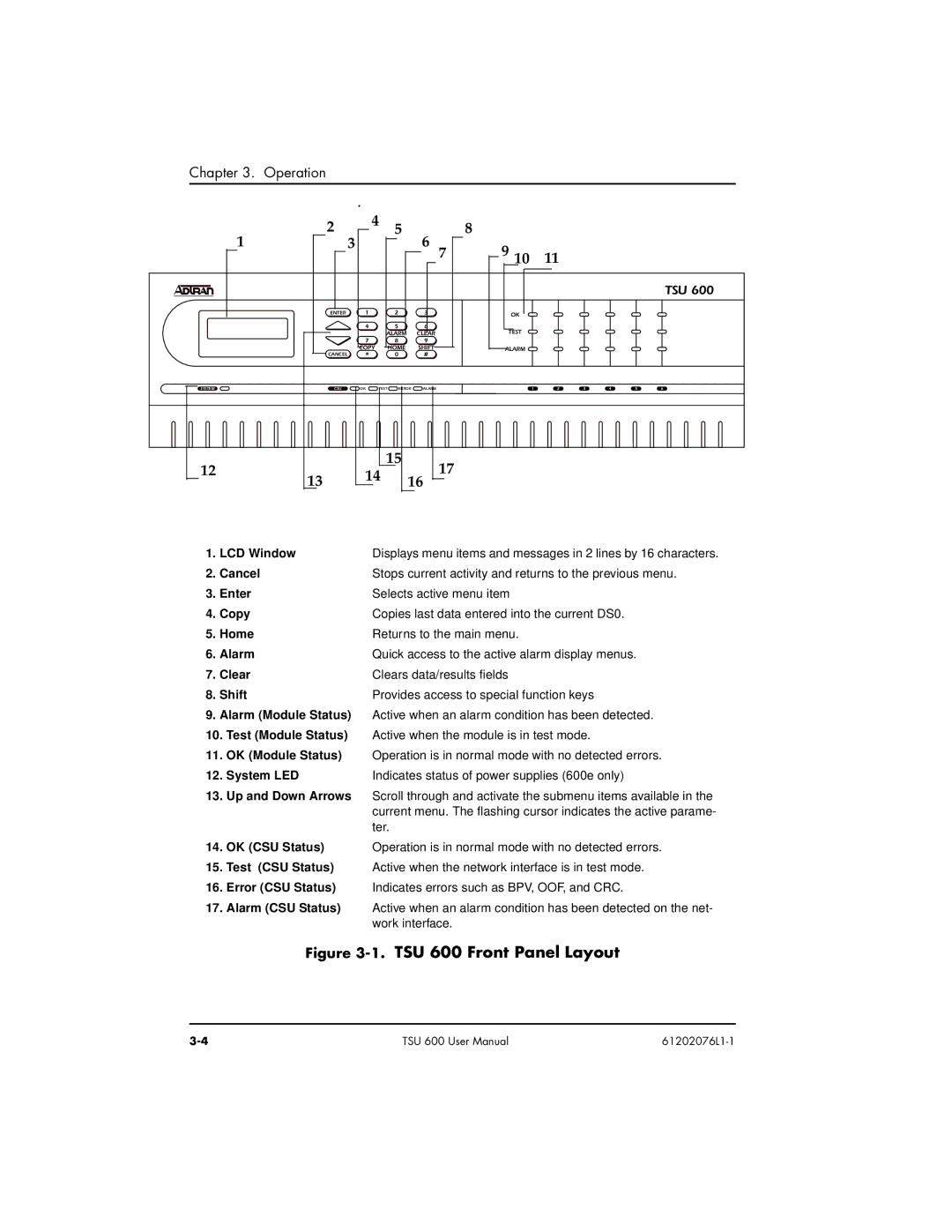
1. LCD Window | Displays menu items and messages in 2 lines by 16 characters. | |
2. | Cancel | Stops current activity and returns to the previous menu. |
3. | Enter | Selects active menu item |
4. | Copy | Copies last data entered into the current DS0. |
5. Home | Returns to the main menu. | |
6. | Alarm | Quick access to the active alarm display menus. |
7. | Clear | Clears data/results fields |
8. | Shift | Provides access to special function keys |
9.Alarm (Module Status) Active when an alarm condition has been detected.
10.Test (Module Status) Active when the module is in test mode.
11.OK (Module Status) Operation is in normal mode with no detected errors.
12. System LED | Indicates status of power supplies (600e only) |
13.Up and Down Arrows Scroll through and activate the submenu items available in the current menu. The flashing cursor indicates the active parame- ter.
14. OK (CSU Status) | Operation is in normal mode with no detected errors. |
15.Test (CSU Status) Active when the network interface is in test mode.
16.Error (CSU Status) Indicates errors such as BPV, OOF, and CRC.
17.Alarm (CSU Status) Active when an alarm condition has been detected on the net- work interface.
Figure 3-1. TSU 600 Front Panel Layout
TSU 600 User Manual |