User’s Guide
Agilent 34970A Data Acquistion/Switch Unit
Page
Flexible Data Acquisition/Switching Features
Convenient Data Logging Features
Front Panel at a Glance
Front-Panel Menus at a Glance
Adrs
Display Annunciators
Use the Menu to
Rear Panel at a Glance
BenchLink Data Logger Software at a Glance
34902A 16-Channel Reed Multiplexer
For detailed information and a module diagram, see
Plug-In Modules at a Glance
34901A 20-Channel Armature Multiplexer
34904A 4x8 Two-Wire Matrix Switch
34903A 20-Channel Actuator/General-Purpose Switch
34905/6A Dual 4-Channel RF Multiplexers
34907A Multifunction Module
For detailed information and module block diagrams, see
34908A 40-Channel Single-Ended Multiplexer
This Book
Contents
Contents
Remote Interface Reference
Application Programs
Quick Start
Quick Start
Check the list of supplied items
Connect the power cord and turn on the instrument
To Prepare the Instrument for Use
To Prepare the Instrument for Use
Installation Procedure
Installing BenchLink Data Logger Software
Installing BenchLink Data Logger Software
On-Line Help System
Creating Installation Floppy Disks
To Connect Wiring to a Module
To Connect Wiring to a Module
DC Current / AC Current
Wire Ohms / RTD / Thermistor
Wire Ohms / RTD
Thermocouple DC Voltage / AC Voltage / Frequency
Set the date
To Set the Time and Date
To Set the Time and Date
Set the time of day
Select the measurement parameters for the selected channel
To Configure a Channel for Scanning
To Configure a Channel for Scanning
Select the channel to be added to the scan list
View the data from the scan
Run the scan and store the readings in non-volatile memory
To Copy a Channel Configuration
To Copy a Channel Configuration
Close the selected channel Open the selected channel
To Close a Channel
To Close a Channel
Select the channel
If the Instrument Does Not Turn On
Verify that there is ac power to the instrument
Verify the power-line voltage setting
Verify that the power-line fuse is good
Replace the fuse-holder assembly in the rear panel
To Adjust the Carrying Handle
To Adjust the Carrying Handle
Bench-top viewing positions
To Rack Mount the Instrument
To Rack Mount the Instrument
Quick Start
Page
Front-Panel Overview
Front-Panel Overview
Front-Panel Menu Reference
Front-Panel Menu Reference
Configure system-related instrument parameters
To Monitor a Single Channel
Enable monitoring on the selected channel
To disable monitoring, press again
To Monitor a Single Channel
Select the scan count
Select the interval scan mode
To Set a Scan Interval
To Set a Scan Interval
To Apply Mx+B Scaling to Measurements
To Apply Mx+B Scaling to Measurements
Select the alarm mode on the selected channel
To Configure Alarm Limits
To Configure Alarm Limits
Select which of the four alarms you want to use
Set the limit value
Read the specified port
To Read a Digital Input Port
To Read a Digital Input Port
Select the Digital Input port
To Write to a Digital Output Port
To Write to a Digital Output Port
Select the totalizer channel
Configure the totalize mode
To Read the Totalizer Count
To Read the Totalizer Count
Output the voltage from the selected DAC
To Output a DC Voltage
To Output a DC Voltage
Select a DAC Output channel
Select the Gpib address
To Configure the Remote Interface
To Configure the Remote Interface
Select the Gpib Hpib interface
Save the changes and exit the menu
Select the RS-232 interface Select the baud rate
Select the parity and number of data bits
Select the flow control method
Store the instrument state
To Store the Instrument State
To Store the Instrument State
Select the storage location
System Overview
Control Output, starting on
Data Acquisition System Overview
Data Acquisition System Overview
Computer and Interface Cable
Advantages Disadvantages
Agilent BenchLink Data Logger
Measurement Software
34970A Data Acquisition / Switch Unit
Plug-In Modules
Signal Routing
Model Number Module Name Common Uses
System Cabling and Connections starting on
System Cabling
Cable Type Common Uses Comments
Transducers and Sensors
Alarm Limits
Switching Topologies
Signal Routing and Switching
Signal Routing and Switching
Multiplexers are available in several types
Channel Open
Internal DMM
Measurement Input
Measurement Input
Measurement Input
Scanning
Scan Count
Scanning With External Instruments
Multifunction Module
+IN
Control Output
Control Output
DAC
Actuator / General-Purpose Switch
Page
Features and Functions
Scanning, starting on
Mx+B Scaling, starting on Alarm Limits, starting on
Scpi Language Conventions
Rules for Using a Channel List
Scpi Language Conventions
Rules for Scanning
Scanning
Scanning
Scanning
Or disable it see Internal DMM Disable on
Power Failure
To Build a Scan List From the Front Panel
Adding Channels to a Scan List
To Build a Scan List From the Remote Interface
Scan Interval
Sweep the scan list 2 times
Select the interval timer configuration
See Scan Count on page 86 for more information
Set the scan interval to 5 seconds
Front-Panel Operation
Select the bus once configuration
Group Execute Trigger
Select the external trigger configuration
Ext Trig Connector
On page 86 for more information
Enable monitoring
Select the alarm configuration
Enable the upper limit
Report alarms on Alarm
Remote Interface Operation
Scan Count
Reading Format
Channel Delay
AC Filter Channel Delay
Automatic Channel Delays
Integration Time Channel Delay
Range Channel Delay
Viewing Readings Stored in Memory
Readings
Time maximum was logged
Minimum reading on channel
Time minimum was logged
Maximum reading on channel
Single-Channel Monitoring
Single-Channel Monitoring
ROUTMONDATA?
Scanning With External Instruments
Scanning With External Instruments
Scanning With External Instruments
Select the channel advance source
Select the scan interval
General Measurement Configuration
General Measurement Configuration
Measurement Range
MV Range
Measurement Resolution
Integration Time, on page 103 for more information
102
PLC
Custom A/D Integration Time
104
Autozero
Temperature Measurement Configuration
Temperature Measurement Configuration
Measurement Units
Thermocouple Measurements
108
Remote Interface Operation You can use the MEASure? or
To connect an RTD to the module’s screw terminals, see
RTD Measurements
111
To connect a thermistor to the module’s screw terminals, see
Thermistor Measurements
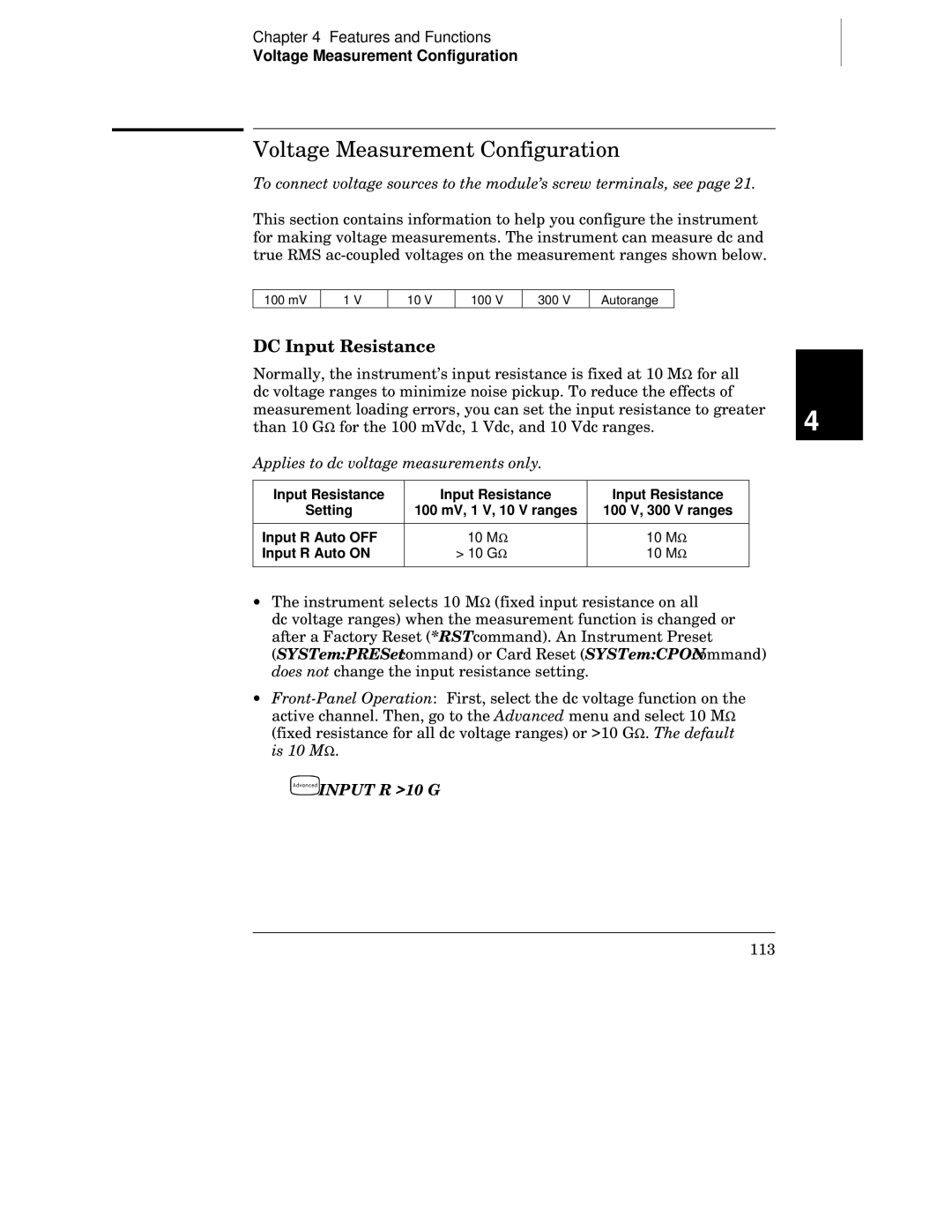
Applies to dc voltage measurements only
Voltage Measurement Configuration
Voltage Measurement Configuration
DC Input Resistance
Applies to ac voltage and ac current measurements only
AC Low Frequency Filter
Sensvoltacband 3,@203 Select the slow filter 3 Hz
To connect resistances to the module’s screw terminals, see
Resistance Measurement Configuration
Resistance Measurement Configuration
Offset Compensation
Current Measurement Configuration
Current Measurement Configuration
Applies to ac current and ac voltage measurements only
Senscurracband 3,@221 Select the slow filter 3 Hz
Sensfreqranglow 3,@203 Select the slow timeout 3 Hz
Frequency Measurement Configuration
Low Frequency Timeout
Frequency Measurement Configuration
Mx+B Scaling
Mx+B Scaling
= − GF x R
121
Alarm Limits
Alarm Limits
Alarm Limits
Alarm Event No Alarm Upper Limit Lower Limit
Then, choose from the following alarm conditions
Viewing Stored Alarm Data
127
Alarms Connector
Using the Alarm Output Lines
Clear all four alarm outputs
Clear alarm output line
Using Alarms With the Multifunction Module
Following commands also see the example on the following
Data read from port decimal
Calccompdata command decimal
Calccompmask command decimal
Result no alarm generated
Digital Input Operations
Digital Input Operations
Read both ports together
Read port
Add port 02 read to scan list
Totalizer Operations
Totalizer Operations
136
137
Write to both ports
Digital Output Operations
Digital Output Operations
Write to port
DAC Output Operations
DAC Output Operations
Three slots six DAC channels
State Storage
System-Related Operations
System-Related Operations
141
Error Conditions
Returns 0 if the self-test is successful or 1 if it fails
Self-Test
Display Control
Set date to June 1
Internal DMM Disable
Real-Time System Clock
Set time to 345 PM
HEWLETT-PACKARD,34970A,0,X.X-Y.Y-Z.Z
Firmware Revision Query
Relay Cycle Count
148
You cannot query the Scpi version from the front panel
Scpi Language Version Query
You can set the Gpib address from the front panel only
Remote Interface Configuration
Remote Interface Configuration
Gpib Address
Remote Interface Selection
You can set the parity from the front panel only
Baud Rate Selection RS-232
Parity Selection RS-232
You can set the baud rate from the front panel only
Flow Control Selection RS-232
154
Calibration Security
Calibration Overview
Calibration Overview
156
Enter new code
Unsecure with old code
Calibration Message
Calibration Count
Factory Reset State
Factory Reset State
Instrument Preset State
Instrument Preset State
Multiplexer Module Default Settings
Multiplexer Module Default Settings
Module Overview
Module Overview
34901A 20-Channel Multiplexer
34901A 20-Channel Multiplexer
Name Function Comments
Slot Number
34902A 16-Channel Multiplexer
34902A 16-Channel Multiplexer
167
34903A 20-Channel Actuator
34903A 20-Channel Actuator
169
34904A 4x8 Matrix Switch
34904A 4x8 Matrix Switch
Name Comments
34905A/6A Dual 4-Channel RF Multiplexers
34905A/6A Dual 4-Channel RF Multiplexers
173
Analog Output DAC
34907A Multifunction Module
Digital Input/Output
Totalize Input
DAC Output
Slot Number 100 200
Digital Input / Output
Totalizer
34908A 40-Channel Single-Ended Multiplexer
34908A 40-Channel Single-Ended Multiplexer
177
178
Remote Interface Reference
Calibration Commands, starting on
Totalizer Commands, starting on
Scanning Overview, starting on
Scpi Command Summary
Scpi Command Summary
Rules for Using scanlist and chlist Parameters
See page 237 for more information
Scpi Command Summary Scan Measurement Commands
Monitor Commands
See page 226 for more information
FORMat
Scpi Command Summary Scan Configuration Commands
See page 235 for more information
Scpi Command Summary Scan Statistics Commands
Scan Memory Commands
See page 233 for more information
See page 239 for more information
Scpi Command Summary Scanning With an External Instrument
See page 219 for more information
Scpi Command Summary Temperature Configuration Commands
See page 223 for more information
Scpi Command Summary Voltage Configuration Commands
See page 224 for more information
Scpi Command Summary Resistance Configuration Commands
Scpi Command Summary Current Configuration Commands
See page 214 for more information
See page 244 for more information
Scpi Command Summary Mx+B Scaling Commands
See page 247 for more information
Scpi Command Summary Alarm Limit Commands
See page 256 for more information
Scpi Command Summary Digital Input Commands
Totalizer Commands
See page 255 for more information
See page 258 for more information
Scpi Command Summary Digital Output Commands
DAC Output Commands
Switch Control Commands
See page 261 for more information
Scpi Command Summary Scan Triggering Commands
State Storage Commands
See page 228 for more information
See page 264 for more information
Scpi Command Summary System-Related Commands
See page 286 for more information
Scpi Command Summary Interface Configuration Commands
Status System Commands
See page 269 for more information
See page 294 for more information
Scpi Command Summary Calibration Commands
Service-Related Commands
See page 292 for more information
Scpi Command Summary Ieee 488.2 Common Commands
Simplified Programming Overview
Simplified Programming Overview
Using the CONFigure Command
Using the MEASure? Command
Using the range and resolution Parameters
Using the INITiate and FETCh? Commands
Using the READ? Command
205
Trigsour EXT Init FETC?
MEASureTEMPerature?5 TCouple,BEJKNRSTDEF
MEASure? and CONFigure Commands
MEASure? and CONFigure Commands
MEASure? Command Syntax
MEASureTEMPerature? THERmistor,2252500010000DEF
MEASureTEMPerature? RTDFRTD,8591DEF
MEASureVOLTageDC? MEASureVOLTageAC? RangeAUTOMINMAXDEF
MEASureCURRentDC? MEASureCURRentAC? RangeAUTOMINMAXDEF
MEASureRESistance? MEASureFRESistance? RangeAUTOMINMAXDEF
On the 34901A multiplexer module
MEASureDIGitalBYTE? @scanlist
MEASureTOTalize? READRRESet ,@scanlist
CONFigureTEMPerature THERmistor,2252500010000DEF
MEASure? and CONFigure Commands CONFigure Command Syntax
CONFigureTEMPerature TCouple,BEJKNRSTDEF
CONFigureTEMPerature RTDFRTD,8591DEF
CONFigureRESistance CONFigureFRESistance RangeAUTOMINMAXDEF
CONFigureVOLTageDC CONFigureVOLTageAC RangeAUTOMINMAXDEF
CONFigureCURRentDC CONFigureCURRentAC RangeAUTOMINMAXDEF
CONFigure? @chlist
CONFigureFREQuency CONFigurePERiod RangeAUTOMINMAXDEF
CONFigureDIGitalBYTE @scanlist
CONFigureTOTalize READRRESet ,@scanlist
SENSeFUNCtion function,@chlist
Setting the Function, Range, and Resolution
Setting the Function, Range, and Resolution
See also General Measurement Configuration in starting on
Setting the Function, Range, and Resolution
Setting the Function, Range, and Resolution
Setting the Function, Range, and Resolution
Setting the Function, Range, and Resolution
SENSeTEMPerature Nplc 0.020.2121020100200MINMAX,@chlist
Temperature Configuration Commands
General Temperature Commands
SENSeTEMPeratureTRANsducer
Temperature Configuration Commands Thermocouple Commands
SENSeTEMPeratureRJUNction? @ch list
Thermistor Commands
Temperature Configuration Commands RTD Commands
SENSe Zeroauto OFFONCEON,@chlist ZEROAUTO? @chlist
Voltage Configuration Commands
See also Voltage Measurement Configuration in starting on
INPut
Current Configuration Commands
Resistance Configuration Commands
See also Current Measurement Configuration in starting on
Frequency Configuration Commands
Frequency Configuration Commands
See also Frequency Measurement Configuration in starting on
Scanning Overview
Scanning Overview
See also Scanning in starting on
Scan Interval
ROUTeSCANSIZE?
Scanning Overview Scanning Commands
TRIGger SOURce BUSIMMediateEXTernalALARm1234TIMer SOURce?
ROUTe Scan @scanlist SCAN?
ROUTe CHANnelDELay seconds,@ch list CHANnelDELay? @chlist
TRIGger TIMer secondsMINMAX TIMer?
TRIGger COUNt countMINMAXINFinity COUNt?
ABORt
ROUTe
INITiate
FORMat READingALARm Offon READingALARm?
Scanning Overview Reading Format Commands
FORMat READingCHANnel Offon READingCHANnel?
FORMat READingUNIT Offon READingUNIT?
FORMat READingTIME Offon READingTIME?
FORMat READingTIMETYPE ABSoluteRELative READingTIMETYPE?
CALCulateAVERageMAXimum? @chlist
Scanning Overview Scan Statistics Commands
CALCulateAVERageMINimum? @chlist
CALCulateAVERageMINimumTIME? @chlist
CALCulateAVERageCLEar @chlist
CALCulateAVERageAVERage? @chlist
CALCulateAVERagePTPeak? @chlist
CALCulateAVERageCOUNt? @chlist
DATAPOINts?
Scanning Overview Scan Memory Commands
DATAREMove? numrdgs
SYSTemTIMESCAN?
See Reading Format Commands on
FETCh?
Single-Channel Monitoring Overview
Single-Channel Monitoring Overview
ROUTe MONitorSTATe Offon MONitorSTATe?
ROUTe MONitor @channel MONitor?
ROUTeMONitorDATA?
Scanning With an External Instrument
TRIGger SOURce BUSIMMediateEXTernalTIMer SOURce?
TRIGger COUNt valueMINMAXINFinity COUNt?
Scanning With an External Instrument
INSTrument
INSTrumentDMMINSTalled?
Mx+B Scaling Overview
Mx+B Scaling Overview
See also Mx+B Scaling in starting on
CALCulate
Mx+B Scaling Overview Mx+B Scaling Commands
CALCulateSCALeOFFSetNULL @chlist
Alarm System Overview
Alarm System Overview
See also Alarm Limits in starting on
Alarm System Overview
Calclimitupper MAX,@101LOWER 9,@101LOWERSTATE on
OUTPut ALARm1234SOURce @chlist ALARm1234SOURce?
Alarm System Overview Alarm Limit Commands
CALCulate LIMitUPPer value,@ch list LIMitUPPer? @chlist
CALCulate LIMitLOWer value,@ch list LIMitLOWer? @chlist
SYSTemALARm?
OUTPut ALARmMODE LATChTRACk ALARmMODE?
Alarm System Overview Alarm Output Commands
OUTPut ALARmSLOPe NEGativePOSitive ALARmSLOPe?
COMPareDATA? @chlist
Digital I/O Alarm Commands
COMPareMASK mask,@chlist COMPareMASK? @chlist
See also Digital Input Operations in starting on
Digital Input Commands
SENSeDIGitalDATABYTEWORD? @chlist
SENSe TOTalizeTYPE READRRESet,@chlist TOTalizeTYPE? @chlist
Totalizer Commands
See also Totalizer Operations in starting on
SENSeTOTalizeCLEarIMMediate @chlist
Commands see Reading Format Commands on
SENSeTOTalizeDATA? @chlist
SOURce
Digital Output Commands
DAC Output Commands
SOURceDIGitalSTATe? @chlist
Switch Control Commands
SYSTemCPON 100200300ALL
ROUTeDONE?
This is equivalent to pressing from the front panel
SAV
State Storage Commands
RCL
MEMorySTATeDELete
MEMorySTATe Name 12345 ,name NAME?
MEMorySTATeVALid?
RECallAUTO?
MEMoryNSTates?
SYSTemDATE?
System-Related Commands
See also System-Related Operations in starting on
SYSTemDATE yyyy,mm,dd
SYSTemCTYPe?
IDN?
DISPlay
DISPlay Offon DISPlay?
DISPlayTEXTCLEar
INSTrument DMM Offon
SYSTemPRESet
See for a complete listing of the 34970A error messages
SYSTemERRor?
SYSTemVERSion?
Interface Configuration Commands
RS-232 Configuration Overview
RS-232 Interface Configuration
RS-232 Interface Configuration
RS-232 Flow Control Modes
Connection to a Computer or Terminal
RS-232 Data Frame Format
RS-232 Troubleshooting
S0=1
Modem Communications
Modem Communications
For more information, see Flow Control Selection on
Scpi Status System
What is a Condition Register?
What is an Event Register?
What is an Enable Register?
Agilent 34970A Status System
Definition
Status Byte Register
Bit Definitions Status Byte Register
Decimal Bit Number
Using *STB? to Read the Status Byte
Using Service Request SRQ and Serial Poll
To Interrupt Your Bus Controller Using SRQ
Using the Message Available Bit MAV
To Determine When a Command Sequence is Completed
Bit Definitions Questionable Data Register
Questionable Data Register
Scpi Status System
Bit Definitions Standard Event Register
Standard Event Register
Scpi Status System
Bit Definitions Alarm Register
Alarm Register
Bit Definitions Standard Operation Register
Standard Operation Register
Status Byte Register Commands
Status System Commands
See the table on page 277 for the register bit definitions
See the table on page 280 for the register bit definitions
Questionable Data Register Commands
See the table on page 282 for the register bit definitions
Status System Commands Standard Event Register Commands
STATusALARmENABle enablevalue STATusALARmENABle?
Status System Commands Alarm Register Commands
STATusALARmCONDition?
STATusALARmEVENt?
STATusOPERationCONDition?
Status System Commands Standard Operation Register Commands
STATusOPERationENABle enablevalue STATusOPERationENABle?
See the table on page 285 for the register bit definitions
PSC
Miscellaneous Status Register Commands
STATusPRESet
DATAPOINtsEVENtTHReshold numrdgs DATAPOINtsEVENtTHReshold?
CALibrationSECureCODE newcode
Calibration Commands
CALibration?
CALibrationCOUNt?
CALibrationVALue value CALibrationVALue?
CALibrationSECureSTATe OFFON,code CALibrationSECureSTATe?
CALibrationSTRing quotedstring
CALibrationSTRing?
DIAGnosticRELayCYCLes? @chlist
Service-Related Commands
DIAGnosticDMMCYCLes?
DIAGnosticDMMCYCLesCLEar
WAI
An Introduction to the Scpi Language
An Introduction to the Scpi Language
Command Format Used in This Manual
Using the MIN and MAX Parameters
Command Separators
Scpi Command Terminators
Querying Parameter Settings
IEEE-488.2 Common Commands
Scpi Parameter Types
301
Using Device Clear
Using Device Clear
Error Messages
Error Messages
Execution Errors
124
Execution Errors 114
121
123
213
Execution Errors 168
178
211
410
Execution Errors 230
310
350
Instrument Errors
225
Instrument Errors 221
226
281
Instrument Errors 261
271
272
305
Instrument Errors 303
306
512
Instrument Errors 501
502
511
603
Self-Test Errors
601
602
Calibration Errors
722
Calibration Errors 710
720
721
903
Plug-In Module Errors
901
902
318
Application Programs
Application Programs
Example Programs for Excel
Example Programs for Excel
VISAaddr =
Excel 7.0 Example takeReadings Macro
323
324
Dim columnIndex As Integer
Excel 7.0 Example ScanChannels Macro
326
327
Example Programs for C and C++
Example Programs for C and C++
++ Example dacout.c
++ Example statreg.c
331
332
Tutorial
Tutorial
Matrix Switching, starting on
System Cabling and Connections
Cable Specifications
System Cabling and Connections
Cable Type Nominal Impedance Capacitance Attenuation
Ft 2 conductors
Grounding Techniques
Shielding Techniques
Separation of High-Level and Low-Level Signals
Sources of System Cabling Errors
Copper-to Approx. ∝V / C
Discussion of integration time
Where
Voltage Measured = √ V + Noise
Measurement Fundamentals
Measurement Fundamentals
NMR
Integration Time PLCs
RTD
Temperature Measurements
Measurement Fundamentals
Internal DMM
Internal DMM Ice Bath
349
Measurement Fundamentals
Copper Constantan
Temperature Probe Type Pos + Lead Neg Lead
Iron Constantan
Nickel-Chromium Nickel-Aluminum
Sources of Error in Thermocouple Measurements
Without Shield
DC Voltage Measurements
Or greater see page 103 for a discussion of integration time
Sources of Error in DC Voltage Measurements
Connection a Connection B
Rs + Ri
358
AC Voltage Measurements
360
361
Sources of Error in AC Voltage Measurements
363
For low frequencies
+ Noise
Measurement Fundamentals
Current measurements are allowed only on the 34901A module
Current Measurements
Sources of Error in AC Current Measurements
Sources of Error in DC Current Measurements
Resistance Measurements
370
Measurement Fundamentals
Insulating Material Resistance Range Moisture Absorbing
Sources of Error in Resistance Measurements
Strain Gage Measurements
HI Source HI Sense LO Sense LO Source
DMM Sensitivity
Strain
Frequency and Period Measurements
Sources of Error in Frequency and Period Measurements
Low-Level Signal Multiplexing and Switching
Low-Level Signal Multiplexing and Switching
Two-Wire Multiplexers
One-Wire Single-Ended Multiplexers
Four-Wire Multiplexers
Signal Routing and Multiplexing
Sources of Error in Multiplexing and Switching
Module Bank
Actuators and General-Purpose Switching
Actuators and General-Purpose Switching
RC Protection Networks
Snubber Circuits
Using Varistors
Using Attenuators
Matrix Switching
Matrix Switching
Matrix Module
Combining Matrices
RF Signal Multiplexing
RF Signal Multiplexing
Insertion Loss 75Ω
Sources of Error in RF Switching
Digital Input
Multifunction Module
Multifunction Module
Digital Output
Driving External Switches
Using an External Pull-Up
Totalizer
Totalizer Errors
Voltage DAC Output
DAC Errors
Relay Life and Preventative Maintenance
Relay Life and Preventative Maintenance
Relay Load
Relay Life
Replacement Strategy
Switching Frequency
402
Specifications
DC, Resistance, and Temperature Accuracy Specifications
DC, Resistance, and Temperature Accuracy Specifications
DC Measurement and Operating Characteristics
DC Measurement and Operating Characteristics
AC Accuracy Specifications
AC Accuracy Specifications
AC Measurement and Operating Characteristics
AC Measurement and Operating Characteristics
Measurement Rates and System Characteristics
Measurement Rates and System Characteristics
Module Specifications
Module Specifications
34905A, 34906A
Crosstalk 75 Ω
Typical AC Performance Graphs
Typical AC Performance Graphs
Insertion Loss 75 Ω
34907A
Software Specifications
Product and Module Dimensions
Product and Module Dimensions
To Calculate Total Measurement Error
To Calculate Total Measurement Error
415
Sensitivity
Interpreting Internal DMM Specifications
Interpreting Internal DMM Specifications
Number of Digits and Overrange
Accuracy
Resolution
Criteria
Hour Accuracy
Temperature Coefficients
Day and 1-Year Accuracy
Configuring for Highest Accuracy Measurements
Configuring for Highest Accuracy Measurements
420
Index
Totalize Threshold jumper, 135, 175 totalizer reset mode
Index
423
424
425
426
427
428
429
430
431
432
433
434
U T I O N
Declaration of Conformity