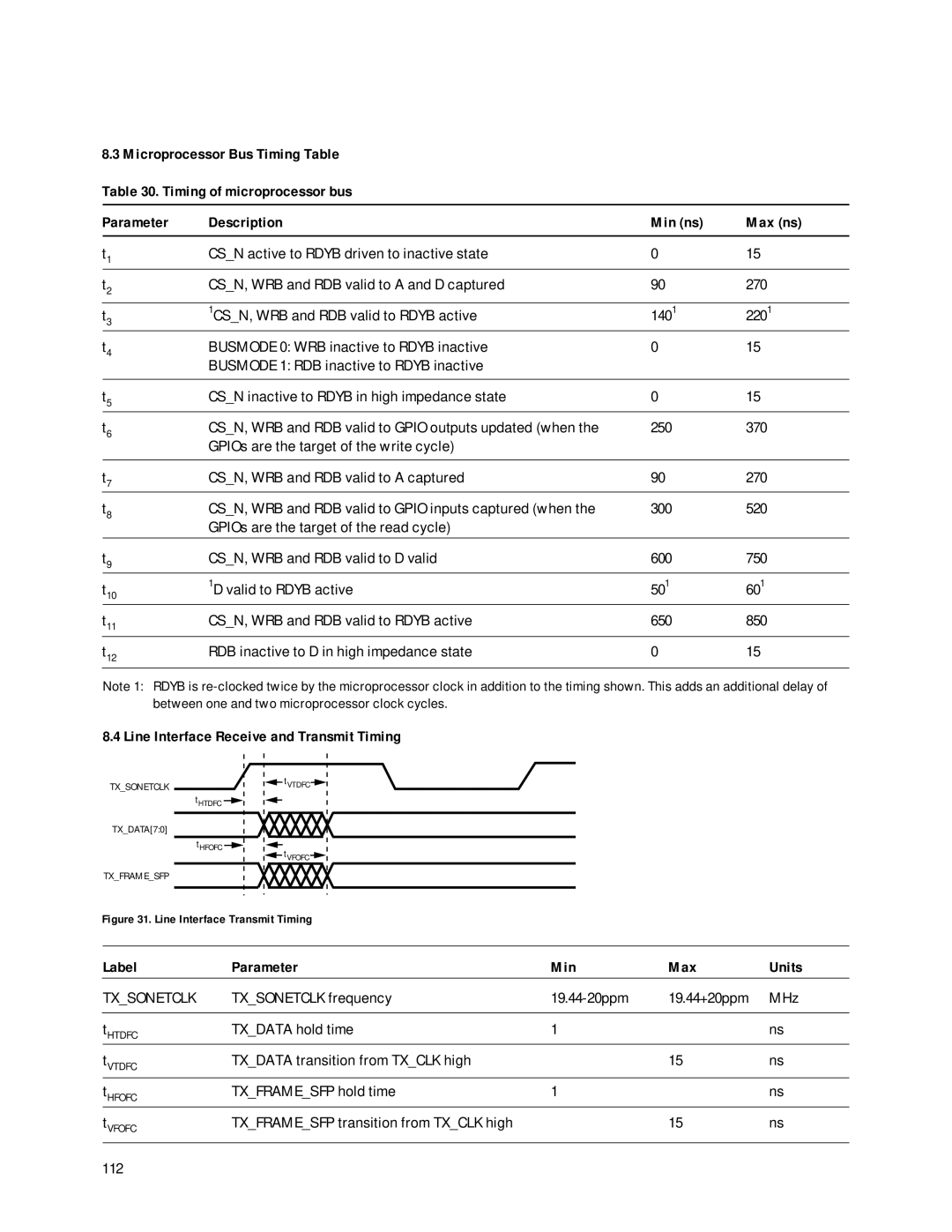
HDMP-3001 specifications
Agilent Technologies, a prominent name in electronics and measurement technology, offers a wide range of products that cater to various industries. Among its notable offerings is the HDMP-3001, a high-speed, serial data transceiver designed to facilitate robust communications in electronic systems. The HDMP-3001 stands out with its ability to handle high bandwidths, making it particularly suited for applications requiring rapid data transfer, such as telecommunications, computer networking, and high-performance computing.One of the main features of the HDMP-3001 is its advanced signaling technology. By employing differential signaling, the transceiver minimizes electromagnetic interference and enhances signal integrity. This is crucial in environments with multiple electronic devices operating simultaneously, as it ensures data is transmitted clearly and without degradation.
The HDMP-3001 operates at a maximum data rate of 1 Gbps, allowing for efficient data transfer over short distances. This capability is coupled with a flexible architecture that enables users to configure the transceiver for various applications. The device supports both point-to-point and point-to-multipoint configurations, giving engineers the versatility they need in designing communication links.
Moreover, the HDMP-3001 features on-chip clock recovery functionality, which simplifies system design by reducing the number of external components needed. This built-in feature allows the transceiver to maintain synchronization even as data rates increase, further enhancing performance.
The low power consumption characteristic of the HDMP-3001 is another notable advantage. This makes it an attractive choice for battery-operated devices and systems where power efficiency is critical. The transceiver’s design ensures optimal performance while minimizing heat generation and power draw, enabling longer operational lifetimes.
In terms of physical characteristics, the HDMP-3001 comes in a compact, surface-mount package, allowing for easier integration into various circuit board designs. The small form factor, combined with its innovative technology, makes it a popular choice among engineers seeking to improve data transmission reliability without compromising on space or power constraints.
Overall, Agilent Technologies' HDMP-3001 is a formidable solution for high-speed serial data transmission, characterized by its robust performance, low power consumption, and versatile configuration options. With these features, it continues to be an essential component in the evolving landscape of electronic communications.

