17 |
3.5 Wiring the Fault Alarm Contact
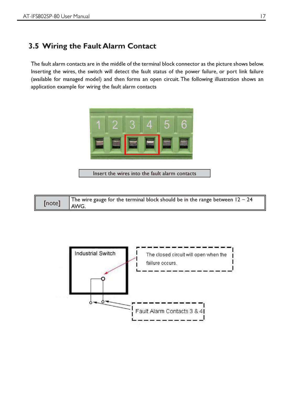
The fault alarm contacts are in the middle of the terminal block connector as the picture shows below. Inserting the wires, the switch will detect the fault status of the power failure, or port link failure (available for managed model) and then forms an open circuit. The following illustration shows an application example for wiring the fault alarm contacts
Insert the wires into the fault alarm contacts
[note]
The wire gauge for the terminal block should be in the range between 12 ~ 24 AWG.